Change of the current through potentiometer
Task number: 2340
Even though potentiometer is mostly known for its ability to regulate voltage on appliance, we can show that potentiometer can also change current flowing through some appliance.
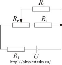
In which interval can we regulate current flowing through resistor R3 in the circuit shown below? What voltage is on resistor R3 at the outer points of this interval? Wiper of the potentiometer can be moved to any location.
U = 30 V, R1 = 100 Ω, R2 = 20 Ω, R3 = 1200 Ω, Rp = 105 Ω.
Hint
To determine the interval we will need to know the values of the outer points.
Let’s compute these values when the wiper is on the left and on the right of the potentiometer.
Breakdown
To determine in which interval is possible to regulate the current flowing through the resistor R3, we will determine the values of the current in outer points of this interval. We will move the wiper to its outer positions A and B.
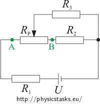
We will compute the current that goes through R3 and voltage for this potentiometer for two different circuits. During calculations we will use the characteristics for integrations in series and parallel.
Solution – Wiper in position A
We will move the wiper of the potentiometer to the position A and we will redraw the integration in a way that we can easily work with:
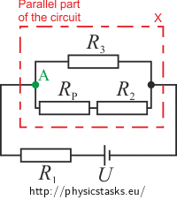
To determine the current I3A flowing through the resistor R3 we will compute the total resistance of the parallel part Rx first:
\[\frac{1}{R_x}\,=\,\frac{1}{R_3}\,+\frac{1}{R_P+R_2}\,=\,\frac{R_P+R_2+R_3}{R_3\left(R_P+R_2\right)}\] \[R_x\,=\,\frac{R_3\left(R_P+R_2\right)}{R_P+R_2+R_3}\,.\tag{1}\]Total voltage in series is equal to the sum of the voltages on every element. For total voltage we can write:
\[U\,=\,U_1\,+\,U_x\,,\]where U1 is the voltage on resistor R1 and Ux is voltage on the parallel part of the circuit.
The value of the current flowing through the part with appliances in series is the same:
\[I_1\,=\,I_x\hspace{10px}\Rightarrow\hspace{10px}\frac{U_1}{R_1}\,=\,\frac{U_x}{R_x}\,.\]Therefore:
\[R_1U_x\,=\,R_xU_1\,.\]From equation for the total voltage we will express U1 = U - Ux and substitute it into the previous equation:
\[R_1U_x\,=\,R_x\left(U\,-\,U_x\right)\,.\]Now we will express voltage Ux:
\[R_1U_x\,+\,R_xU_x\,=\,R_xU\] \[U_x\left(R_1+R_x\right)\,=\,R_xU\] \[U_x\,=\,\frac{R_xU}{R_1+R_x}\,.\]Voltage Ux is the voltage on the parallel part of circuit as well as on resistor R3 (voltage of integration in parallel is the same on every branch). Therefore:
\[I_\mathrm{3A}\,=\,\frac{U_x}{R_3}\,.\]From substituting Ux we will get equation for calculating of the current I3A:
\[I_\mathrm{3A}\,=\,\frac{R_xU}{R_3\left(R_1+R_x\right)}\,.\]Now we will also substitute the formula (1) for calculating resistance of the parallel part of the integration Rx:
\[I_\mathrm{3A}\,=\,\frac{\frac{R_3\left(R_P+R_2\right)}{R_P+R_2+R_3}\,U}{R_3\left(R_1+\frac{R_3\left(R_P+R_2\right)}{R_P+R_2+R_3}\right)}\,.\]Now we will get the final formula for computation of the current I3A:
\[I_\mathrm{3A}\,=\,\frac{\left(R_P+R_2\right)\,U}{R_1R_3+\left(R_1+R_3\right)\left(R_P+R_2\right)}\,.\]Solution – Wiper in position B
We will redraw the schematic with wiper in position B:
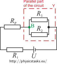
Because voltage is the same on branches of the parallel part (Uy = U3) for current I3 flowing through resistor R3B we can write:
\[I_\mathrm{3B}\,=\,\frac{U_y}{R_3}\,,\tag{2}\]where Uy is voltage on parallel part of the integration.
Total voltage in integration with elements in series is equal to the sum of voltages on individual elements. Therefore:
\[U\,=\,U_1\,+\,U_P\,+\,U_y\hspace{10px}\Rightarrow\hspace{10px}U_y\,=\,U\,-\,U_1\,-\,U_P\,.\]In series the total current is equal to the currents flowing through individual elements:
\[I\,=\,I_1\,=\,I_P\,.\]From Ohm’s law the current flowing through the appliance is equal to the voltage on appliance divided by its resistance:
\[I\,=\,I_1\,=\,\frac{U_1}{R_1}\hspace{50px}I\,=\,I_P\,=\,\frac{U_P}{R_P}\,.\]Formula for voltage in the parallel part can be rewritten to:
\[U_y\,=\,U\,-\,R_1I\,-\,R_PI\] \[U_y\,=\,U\,-\,\left(R_1\,+\,R_P\right)I\,.\tag{3}\]From Ohm’s law we know that the value of the total current I flowing through the circuit equals to the fraction of total voltage U and total resistance R of the circuit:
\[I\,=\,\frac{U}{R}\,.\]To calculate the total current I we need to calculate the total resistance R of the system.
For parallel part of integration we can say:
\[\frac{1}{R_y}\,=\,\frac{1}{R_2}\,+\,\frac{1}{R_3}\,=\,\frac{R_2+R_3}{R_2R_3}\] \[R_y\,=\,\frac{R_2R_3}{R_2+R_3}\,.\]Total resistance R is:
\[R\,=\,R_1\,+\,R_P\,+\,R_y\,=\,R_1\,+\,R_P\,+\,\frac{R_2R_3}{R_2+R_3}=\,\frac{\left(R_1+R_P\right)\left(R_2+R_3\right)+R_2R_3}{R_2+R_3}\,.\]We will substitute this R into the formula for total current of the system:
\[I\,=\,\frac{U}{R}\,=\,\frac{U}{\frac{\left(R_1+R_P\right)\left(R_2+R_3\right)+R_2R_3}{R_2+R_3}}\,.\]Let’s modify it:
\[I\,=\,\frac{U\left(R_2+R_3\right)}{\left(R_1+R_P\right)\left(R_2+R_3\right)+R_2R_3}\,.\]We will substitute this result into formula (3) for voltage in the parallel part of the circuit:
\[U_y\,=\,U\,-\,\left(R_1\,+\,R_P\right)\frac{U\left(R_2+R_3\right)}{\left(R_1+R_P\right)\left(R_2+R_3\right)+R_2R_3}\,.\]After modifying we will get:
\[U_y\,=\,\frac{R_2R_3U}{\left(R_1+R_P\right)\left(R_2+R_3\right)+R_2R_3}\,.\]We will substitute this Uy into formula (2) and get the desired current I3B:
\[I_\mathrm{3B}\,=\,\frac{U_y}{R_3}\,=\,\frac{\frac{R_2R_3U}{\left(R_1+R_P\right)\left(R_2+R_3\right)+R_2R_3}}{R_3}\,=\,\frac{R_2U}{\left(R_1+R_P\right)\left(R_2+R_3\right)+R_2R_3}\,.\]Solution – Wiper in position B (easier solution)
We will compare the circuit with wiper in positions A and B
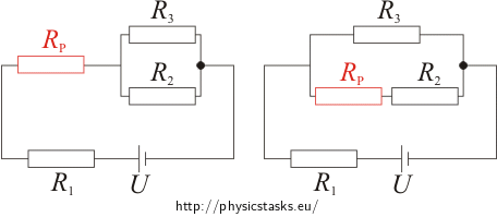
We can see from the picture:
a) a) Instead of potentiometer in series RP and resistor R2 we have now resistor R2 in the parallel branch. Total resistance of this branch is R2.b) b) Potentiometer RP has moved behind the resistor R1. Therefore these two are in series and the total resistance of this part is R1 + RP.Formula for calculating the current I3B flowing through the resistor R3 with wiper of the potentiometer in position B can be gained by altering the final result of Solution 1.
\[I_\mathrm{3A}\,=\,\frac{\left(R_P+R_2\right)\,U}{R_1R_3+\left(R_1+R_3\right)\left(R_P+R_2\right)}\]Instead of RP + R2 we will substitute just R2 (to see a)) and we will replace R1 with R1 + RP (to see b)). Therefore:
\[I_\mathrm{3B}\,=\,\frac{R_2\,U}{\left(R_1+R_P\right)R_3+\left[\left(R_1+R_P\right)+R_3\right]R_2}\,.\]Now we will modify the denominator (we will factor out expression (R1 + RP)) and get the same result as in the previous part of solution:
\[I_\mathrm{3B}\,=\,\frac{R_2\,U}{\left(R_1+R_P\right)\left(R_2+R_3\right)+R_2R_3}\,.\]Numerical substitution
The formulas that we got in the two parts of solution
\[I_{3A}\,=\,\frac{\left(R_P+R_2\right)\,U}{R_1R_3+\left(R_1+R_3\right)\left(R_P+R_2\right)}\] \[U_{3A}\,=\,I_{3A}R_3\] \[I_{3B}\,=\,\frac{R_2U}{\left(R_1+R_P\right)\left(R_2+R_3\right)+R_2R_3}\] \[U_{3B}\,=\,I_{3B}R_3,\]We will substitute the values from the assignment
U = 30 V, R1 = 100 Ω, R2 = 20 Ω, R3 = 1200 Ω, Rp = 105 Ω:
\[I_\mathrm{3A}\,=\,\frac{125{\cdot} 30}{120000+1300{\cdot} 125}\,\mathrm{A}\,=\,13{,}3{\cdot} 10^{-3}\,\mathrm{A}\,=\,13{,}3\,\mathrm{mA}\] \[U_\mathrm{3A}\,=\,13{,}3{\cdot} 10^{-3}\cdot 1200\,\mathrm{V}\,=\,16\,\mathrm{V}\] \[I_\mathrm{3B}\,=\,\frac{20{\cdot} 30}{205{\cdot} 1220+20{\cdot} 1200}\,\mathrm{A}\,=\,2{,}2{\cdot} 10^{-3}\,\mathrm{A}\,=\,2{,}2\,\mathrm{mA}\] \[U_\mathrm{3B}\,=\,2{,}2{\cdot} 10^{-3}\cdot 1200\,\mathrm{V}\,=\,2{,}6\,\mathrm{V}\,.\]Answer
Current flowing through the resistor R3 can be regulated in the interval from 2,2 mA to 13,3 mA. Values of voltage on resistor R3 in outer points of the interval are 16 V and 2,6 V where higher value of voltage corresponds with the lower value of the current.
Value of the current in a general position of the wiper
We stated that the current I3 will have minimum and maximum in the outer positions of the wiper. Now we need to verify if this statement is true.
We will redraw the integration with the wiper in a general position:
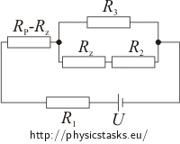
The sum of the resistances of the resistors RP - Rz and Rz is equal to resistance of potentiometer RP. Resistance of the resistor Rz can gain values from 0 Ω to 105 Ω (resistance of potentiometer RP).
In a same way as in the third part of the solution for current I3A
\[ I_\mathrm{3A}\,=\,\frac{\left(R_P+R_2\right)\,U}{R_1R_3+\left(R_1+R_3\right)\left(R_P+R_2\right)} \]We will modify the formula in a way that allows for a general position of the wiper. We will replace the term (RP+R2) with (Rz+R2) and R1 with term (RP-Rz)+R1. Therefore:
\[I_3\,=\,\frac{\left(R_z+R_2\right)\,U}{\left[\left(R_P-R_z\right)+R_1\right]R_3+\left[\left(R_P-R_z\right)+R_1+R_3\right]\left(R_z+R_2\right)}\,.\]We can modify the denominator of the fraction and get the final equal for calculating the current I3 for the wiper in general position:
\[I_3\,=\,\frac{\left(R_z+R_2\right)U}{\left(R_P-R_z+R_1\right)\left(R_3+R_z+R_2\right)+R_3\left(R_z+R_2\right)}\,.\]Now we can modify the fraction by factoring out in front of brackets and multiplying the brackets in a way where the terms Rz and Rz2 are separate:
\[ I_3\,=\,\frac{R_zU+R_2U}{-R_z^2+R_z\left(R_P+R_1-R_2\right)+\left[\left(R_P+R_1\right)\left(R_3+R_2\right)+R_3R_2\right]}\,. \]In order to determine the minimum and maximum of current I3 we must differentiate this formula by Rz. For derivative of fraction of two functions f, g, where g ≠ 0 we can write:
\[ \left(\frac{f}{g}\right)^,\,=\,\frac{f^,g-fg^,}{g^2}\,. \]Note: Overview of basic formulas for differentiation can be found in assignment Electric Eel.
Given that the denominator is not zero we can use this formula for derivative of fraction:
\[ f\,=\,U\left(R_z\,+\,R_2\right) \] \[ g\,=\,-R_z^2+R_z\left(R_P+R_1-R_2\right)+\left(R_P+R_1\right)\left(R_3+R_2\right)+R_3R_2\,. \]Therefore:
\[f^,\,=\,U\] \[g^,\,=\,-2R_z\,+\,\left(R_P\,+\,R_1\,-\,R_2\right)\,,\]where \(f^,\), \(g^,\) are functions\(f\), \(g\) differentiated by \(R_z\).
Because function g is not zero for its square root we can write:
\[g^2\,>\,0\,.\]Now we will look how is it with value of \(f^,g-fg^,\):
\[f^,g=U\left(-R_z^2+R_z\left(R_P+R_1-R_2\right)+\left(R_P+R_1\right)\left(R_3+R_2\right)+R_3R_2\right)\] \[fg^,=U\left(R_z\,+\,R_2\right)\left[-2R_z\,+\,\left(R_P\,+\,R_1\,-\,R_2\right)\right]\,.\]If we subtract the two functions from each other we will get the result:
\[f^,g-fg^,\,=\,U\left(R_z^2+2R_2R_z+R_PR_3+R_1R_3+R_2^2\right)\,.\]Since resistances R1, R2, RP and voltage U are positive and resistance of resistor Rz is between 0 Ω and resistance RP we can write this about the function \(f^,g-fg^,\):
\[f^,g-fg^,\,>\,0\,.\]Therefore the first derivative \(\frac{dI_3}{dR_z}\) is positive and that is why the function I3 dependent on Rz is increasing.
Our approach to calculating the values of outer points of current I3 was right. Minimum values of current I3 are approached for Rz = 0 Ω. This corresponds to wiper being in position B. Maximum values of current I3 are approached when Rz = RP that is when the wiper is in position A.
Link to a related problem
Try to solve also assignment Potentiometer.


