Young’s Interference Experiment
Task number: 1697
Determine the behaviour of light intensity on the screen during Young's interference experiment, provided that two slits acting like coherent light sources are very narrow compared to their distance.

Determine also the width of interference stripes.
- Assume that the time dependence of electric intensity in the plane of the slits is \(\mathcal{E}_0 e^{i\omega t}.\)
- Do not take into account the diffraction phenomenon on the slits.
- Consider the so called Fraunhofer diffraction, i.e. \(L \gg d\).
Theory
• We consider both linear sources to be coherent. This means that in addition to the same frequency and constant phase difference (in this task the sources are in phase), the magnetic and electric components oscillate in constant directions. Thanks to this, the resulting electric field intensity can be obtained by summing of magnitudes of partial intensities.
• When solving this task we use complex formalism.
• In this case, the slits are sources of cylindrical waves. Their mathematical description is similar to that of the plane waves. The equations have nearly the same form; instead of the scalar product \(\vec{k}\cdot\vec{r}\) in the argument of the exponential there is a standard product \(kr\), where \(r\) is a cylindrical coordinate and the amplitude decreases as \(\sqrt{r}\) \[E = \frac{E_0}{\sqrt{r}} e^{i(\omega t - kr + \varphi_0)},\] where \(E_0\) is a constant with dimension \(\mathrm{V\cdot m^{-\frac{1}{2}}}\).
• At greater distance from the sources, the cylindrical waves can be considered planar and we can determine the intensity of light by using the relation \[ I = \frac{1}{2z_0} EE^\star, \] where the asterisk denotes a complex conjugate and \(z_0 = \sqrt{\frac{\mu_0}{\varepsilon_0}}\) is the impedance of vacuum.
• For small angles \(\delta \ll 1\) it is true that \[ \sin\delta \,\approx\, \tan \delta . \]
Hint 1 – superposition of electric intensity
Determine the magnitude of the electric intensity of a wave created by adding two waves with radius vectors \(l_1\) and \(l_2\).
Determine the complex conjugate of the resulting electric intensity \(E^\star\).
Hint 2 – behaviour of light intensity on the screen
Calculate the dependence of the intensity of light on the path difference \(\Delta l\) according to the relation
\[ I = \frac{1}{2z_0} EE^\star, \]by substituting the electric intensity and the complex conjugate calculated above.
Hint 3 – L ≫ d approximation
Consider that the screen is sufficiently far from the slits.
Evaluate the path difference \(\Delta l\) using the distance \(d\) between the slits and the angle \(\alpha\) between the interfering rays and the normal to the screen.
Hint 4 – width of interference stripes
For small angles \(\alpha\) determine the width of the interference stripes.
How does the width depend on \(L,\lambda\) and \(d\)?
OVERALL SOLUTION
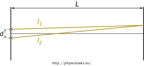
The magnitude of the electric intensity of a wave, propagating from the first slit at a given point of the screen distanced \(l_1\) from this slit, is
\[ E_1 = \frac{E_0}{\sqrt{l_1}} e^{i(\omega t - kl_1)} ~\approx~ \frac{E_0}{\sqrt{L}} e^{i(\omega t - kl_1)}, \]a and the electric intensity at the same point from the second slit, distanced \(l_2\), is
\[ E_2 = \frac{E_0}{\sqrt{l_2}} e^{i(\omega t - kl_2)} ~\approx~ \frac{E_0}{\sqrt{L}} e^{i(\omega t - kl_2)}. \]Given the fact that we consider the screen to be at a great distance, the components \(\sqrt{l_1}, \sqrt{l_2}\) of the loss of amplitudes of electric intensity can be approximated by \({\sqrt {L}}\).
The resulting electric intensity at a given point of the screen is the sum of the magnitudes of these intensities, because they oscillate in the same direction. After more adjusting we obtain
\[ E = E_1 + E_2 = \frac{E_0}{\sqrt{L}} \left( e^{i(\omega t - kl_1)} + e^{i(\omega t - kl_2)}\right) = \] \[ =\frac{E_0}{\sqrt{L}} e^{i(\omega t - kl_1)} \big(1 + e^{-ik(\overbrace{l_2-l_1}^{\mathrm{ozn.\,}\Delta l})} \big)= \frac{E_0}{\sqrt{L}} e^{i(\omega t - kl_1)} \left(1 + e^{-ik\Delta l} \right). \]The complex conjugate of the magnitude of the resulting electric intensity is
\[ E^\star=\frac{E_0}{\sqrt{L}} e^{-i(\omega t - kl_1)} \left(1 + e^{ik\Delta l} \right). \]We substitute the above calculated electric intensities into the relationship of light intensity
\[ I = \frac{1}{2z_0} EE^\star = \frac{E_0^2}{2z_0 L} \underbrace{e^{i(\omega t - kl_1)} e^{-i(\omega t - kl_1)}}_{1} \left(1 + e^{-ik\Delta l} \right)\left(1 + e^{ik\Delta l} \right)= \] \[ \frac{E_0^2}{2z_0 L} \big(1 + e^{ik\Delta l} + e^{-ik\Delta l} + \underbrace{e^{-ik\Delta l} e^{ik\Delta l}}_{1} \big) = \frac{E_0^2}{2z_0 L} \left(2+ e^{ik\Delta l} + e^{-ik\Delta l}\right)= \]We adjust the relation by expressing the complex exponential functions using trigonometric functions and Euler's formula\(e^{i\varphi} = \cos \varphi + i\sin\varphi\).
\[ =\frac{E_0^2}{2z_0 L} \left(2+\cos k \Delta l + i \sin k \Delta l + \cos k \Delta l - i \sin k \Delta l \right) = \] \[ = \frac{E_0^2}{z_0 L}\left(1+\cos k \Delta l \right)= \frac{2E_0^2}{z_0 L}\cos^2 \left(\frac{k \Delta l}{2} \right). \]In the last step, we used the trigonomettric formula \(\small \cos^2 \frac{x}{2} = \frac{1}{2}\left(1+\cos x\right)\).
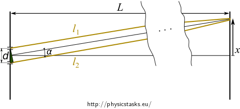
Provided that the screen is sufficiently far from the double slit and the two slits are very close together, the radius vectors \(l_1\) and \(l_2\) are almost parallel to their axis.


The path difference \(\Delta l\) is the shortest side in the indicated green triangle. This triangle is magnified in the picture on the right.
The triangle in this approximation can be considered right-angled, therefore
\[ \Delta l = d \sin \alpha, \]where the angle \(\alpha\) is also the angle between the interfering rays and the normal to the screen.
By substituting into the equation (1) for the intensity of light, we obtain
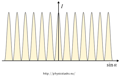
\[ I = \frac{2E_0^2}{z_0 L}\cos^2 \left(\frac{kd \sin \alpha}{2} \right). \]Graph of the function \(I=I(\sin\alpha)\).

We plot the dependence of light intensity as a function of \(\sin \alpha\) which is proportional to the coordinate \(x\).
According to the graph, the intensity is not decreasing with increasing distance from the centre of the screen. This is the result of neglecting the diffraction phenomenon at the slits.
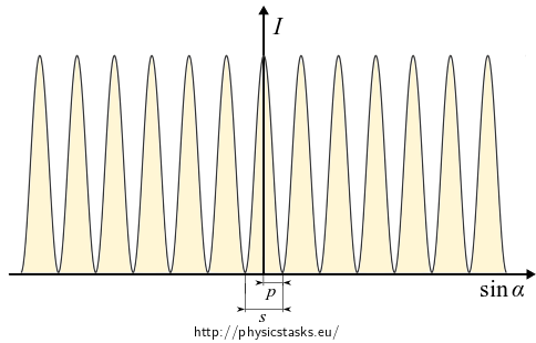
Now we need to determine the width of the interference stripes, i.e. the distance between two adjacent minima (maxima). We use another approximation, for small angles \(\alpha \ll 1\) is
\[\sin\alpha \,\approx\,\tan \alpha = \frac{x}{L}.\]
By substituting \(\frac{x}{L}\) for \(\sin\alpha\) in the relationship (2) we obtain
\[ I = \frac{2E_0^2}{z_0 L}\cos^2 \left(\frac{kdx}{2L} \right), \qquad \mathrm{pro~}\alpha \ll 1. \]
The first intensity minimum occurs for argument \(\frac{\pi}{2}\). Let us determine the coordinate \(x=p\) on the screen corresponding to this argument. We use the relation \(k=\frac{2\pi}{\lambda}\).
\[ \frac{2\pi}{\lambda}\frac{d p}{2L} = \frac{\pi}{2} \quad \Rightarrow \quad p = \frac{L\lambda}{2d}. \]The distance between two adjacent minima (maxima) is twice as big, i.e. the width of the stripe is
\[ s = 2p = \frac{L\lambda}{d}. \]With increasing distance \(L\) between the screen and the slits and with increasing wavelength \(\lambda\) the distance between two interference stripes is greater; on the contrary, with increasing distance between the slits \(d\) the distance is shorter.
Answer
Considering the approximation of a screen at a great distance, we determined the following behaviour of light intensity
\[ I = \frac{2E_0^2}{z_0 L}\cos^2 \left(\frac{kd \sin \alpha}{2} \right), \]where \(\alpha\) is the angle between the normal to screen and the axis of the interfering rays.
Graph \(I=I(\sin\alpha)\).

The determined behaviour of light intensity, as we see in the graph, correctly describes the area near the centre of the screen. In areas further from the centre, a decrease of intensity of the main peaks occurs caused by the diffraction at the slits.
We determined the relation between the width of the interference stripes and other parameters
\[ s \,\approx\, \frac{\lambda L}{d}. \]With increasing distance \(L\) between the screen and the slits and with increasing wavelength \(\lambda\) the distance between two interference stripes is greater; on the contrary, with increasing distance between the slits \(d\) the distance is shorter.
Link – Young's diffraction experiment
In the task Young’s Experiment including Impact of Diffraction you can find Young’s interference experiment which considers the diffraction phenomenon.
Link to experiment
If you would like to know how the interference pattern looks like in a real experiment, look at the Double-Slit Experiment.


