Young’s Double-slit Diffracion Experiment – Alternative Approach
Task number: 1971
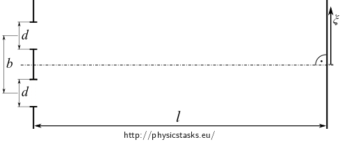
Assess the distribution of the intensity of light on a screen during Young’s interference experiment. Two parallel slits of width \(d\) are located at a distance of \(b\). The screen is at a distance \(l\) from the slits.

- A plane harmonic wave falls onto the double-slit with its linear polarization being oriented along the slits.
- Solve the task in the Fraunhofer approximation of diffraction.
- Include the impact of diffraction of light at each of the slits due to the not negligible width of the slits.
Approach the double slit as two independent slits of not negligible width that are localted next to each other and account for the interference of the two waves coming out of the two slits. The diffraction at a single slit is described in this task.
Analysis
For the calculation, we need the distribution of the electric field on the screen for diffraction of light at a single slit:
\[ E(\alpha) = \frac{E_0d}{\sqrt{l}} e^{i(\omega t - k\sqrt{l^2 + \xi^2})} \frac{\sin\psi}{\psi}, \qquad \mathrm{where\,} \psi = k\frac{d}{2}\sin\alpha. \tag{1}\]The single slit in the solution of the task above was located at the optical axis of the experiment. In our situation there are two slits — one is located above and the other below the optical axis. Due to this difference, the electric field from one slit will be gainig phase and the electric field from the other slit will lag behind in phase at a given point on the screen in comparison with the electric field from the single slit located at the optical axis as described with Equation (1).
Hint 1 — Electric field of slits at different places
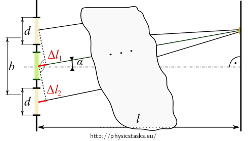
We can describe the distribution of the electric field from the slit that was located at the optical axis (indicated in green on the figure below):
\[ E(\alpha) = \frac{E_0d}{\sqrt{l}} e^{i(\omega t - k\sqrt{l^2 + \xi^2})} \frac{\sin\psi}{\psi}, \qquad \mathrm{where\,} \psi = k\frac{d}{2}\sin\alpha. \]
Adjust this formula to get the electric fields \(E_1(\alpha)\), \(E_2(\alpha)\) of light coming out of the two slits that are positioned \(b/2\) above and below the optical axis. Make use of the Fraunhofer approximation: \(L \gg b+d\) – focus on the difference of the path lengths of the rays from the two slits with respect to the central slit and consider the rays in the figure to be practically parallel near the slits.
Hint 2 — Superposition of electric fields
The resulting electric field on the sceen is a superposition of the electric fields coming out of the two slits. Find the resulting electric field as the sum of the electric fields \(E_1(\alpha), E_2(\alpha)\) and simplify the obtained expression.
Hint 3 — Light intensity on the screen
The wavefronts of the cylindrical waves coming out of the slits can be considered to be planar at the distant screen. The intensity of light on the screen can thus be calculated using the formula for plane waves:
\[I = \frac{1}{2z_0} E_r E_r^\star.\]COMPLETE SOLUTION
For the calculation, we need the distribution of the electric field on the screen for diffraction of light at a single slit:
\[ E(\alpha) = \frac{E_0d}{\sqrt{l}} e^{i(\omega t - k\sqrt{l^2 + \xi^2})} \frac{\sin\psi}{\psi}, \qquad \mathrm{where\,} \psi = k\frac{d}{2}\sin\alpha. \,\,\,(1) \]The single slit in the solution of the task above was located at the optical axis of the experiment. In our situation there are two slits — one is located above and the other below the optical axis. Due to this difference, the electric field from one slit will be gainig phase and the electric field from the other slit will lag behind in phase at a given point on the screen in comparison with the electric field from the single slit located at the optical axis as described with Equation (1).
The figure below shows the position of single slit described by (1) in green and the two actual slits given in this task in beige.

-
The path of the ray coming out of the slit that is shifted by \(b/2\) up is shorter by \(\Delta l_1\) with respect to the ray coming out of the central slit:
\[\Delta l_1 = - \frac{b}{2} \sin \alpha\] -
The path of the ray coming out of the slit that is shifted by \(b/2\) down is longer by \(\Delta l_2\) with respect to the ray coming out of central slit:
\[\Delta l_2 = \frac{b}{2} \sin \alpha\]
The length of the path of the wave coming out of the central slit is given by the Pythagoras’ relation \(\sqrt{l^2 + \xi^2}\) in the exponent in Equation (1). We obtain the electric field coming out of the two shifted slits by adding the path differences to this path length:
\[ \begin{eqnarray} E_1(\alpha) &=& \frac{E_0d}{\sqrt{l}} e^{i\left[\omega t - k\left(\sqrt{l^2 + \xi^2} - \frac{b}{2}\sin \alpha\right)\right]} \frac{\sin\psi}{\psi}, \\ E_2(\alpha) &=& \frac{E_0d}{\sqrt{l}} e^{i\left[\omega t - k\left(\sqrt{l^2 + \xi^2}) + \frac{b}{2}\sin \alpha\right)\right]} \frac{\sin\psi}{\psi}. \end{eqnarray} \]We get the resulting electric field \(E_r\) as the sum of the electric fields \(E_1(\alpha), E_2(\alpha)\):
\[E_r(\alpha) = E_1(\alpha) + E_2(\alpha) = \\ = \frac{E_0d}{\sqrt{l}} e^{i(\omega t - k\sqrt{l^2 + \xi^2})} \frac{\sin\psi}{\psi} \left(e^{ik\frac{b}{2}\sin \alpha} + e^{-ik\frac{b}{2}\sin \alpha} \right),\]Where we have factored out the terms that are the same for both the electric fields.
We abbreviate the phase-difference factor \(\phi = k\frac{b}{2}\sin \alpha\).
Let us rearrange the summation of the exponential functions in the last parentheses separately:
\[ e^{ik\frac{b}{2}\sin \alpha} + e^{-ik\frac{b}{2}\sin \alpha} = e^{i\phi} + e^{-i\phi} = \\ = \cos \phi + i\sin \phi + \cos( -\phi) + i\sin (-\phi) = 2\cos\phi. \]And we have
\[ \begin{array}{ll} E_r(\alpha) = \frac{E_0d}{\sqrt{l}} e^{i(\omega t - k\sqrt{l^2 + \xi^2})} \frac{\sin\psi}{\psi} 2\cos\phi, \qquad \mathrm{where\,} & \psi = k\frac{d}{2} \sin\alpha,\\ & \phi = k\frac{b}{2} \sin\alpha. \end{array} \]We get the distribution of the intensity of light by substituting the resulting electric field \(E_r(\alpha)\) and its complex conjugate into the definition of light intensity:
\[ I = \frac{1}{2z_0} E_r E_r^\star = \overbrace{\frac{2E_0^2 d^2}{z_0l}}^{\mathrm{def.\,}I_0} \underbrace{e^{i(\cdots)}e^{-i(\cdots)}}_{1} \frac{\sin^2 \psi}{\psi^2}\cos^2 \phi. \]And the intensity distribution with respect to the angle \(\alpha\) from the optical axis is:
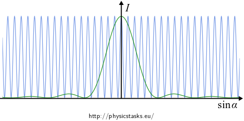
\[ \begin{array}{cl} I = I_0 \color{green}{\frac{\sin^2 \psi}{\psi^2}}\color{blue}{\cos^2 \phi}, \qquad \mathrm{where}\quad & \psi = k\frac{d}{2}\sin \alpha, \\ & \phi = k\frac{b}{2}\sin \alpha. \end{array} \]The intensity is a product of two functions:
-
\(\color{green}{\frac{\sin^2 \psi}{\psi^2}}\), which we have calculated in the task on diffraction of light on a single slit,
-
\(\color{blue}{\cos^2 \phi}\), which we have obtained in the task on interference of light coming out of two slits without the effect of diffraction.

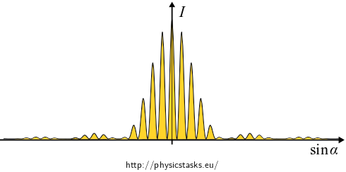
We get below the distribution of the intensity of light as a product of the two functions plotted above.

-
Answer
The distribution of the intensity of light on the screen is
\[ \begin{array}{cl} I = I_0 \frac{\sin^2 \psi}{\psi^2}\cos^2 \phi, \qquad \mathrm{where}\quad & \psi = k\frac{d}{2}\sin \alpha, \\ & \phi = k\frac{b}{2}\sin \alpha, \\ & I_0 = \frac{2E_0^2 d^2}{z_0l}. \end{array} \]
Link – Young’s experiment with diffraction solved by integration
The task can be solved without knowing the diffraction at a single slit by direct integration, see Young’s Experiment including Impact of Diffraction.


