RLC Circuit with Adjustable Capacitance of Capacitor
Task number: 1165
An ideal inductor, a 5 Ω resistor and a capacitor with adjustable capacitance are connected in series to a source of alternating voltage with an effective value of 10 V and with frequency of 50 Hz. The current flowing through the circuit when the capacitance of the capacitor is set to C1 = 100 μF is the same as when the capacitance of the capacitor is set to C2 = 200 μF. Find out the inductance of the inductor and calculate the effective current flowing through the circuit when the capacitance of the capacitor is set to C2.
Hint
Realize what implies the fact that there is the same current flowing through the circuit for two different capacitances of the capacitor. What other quantity must be the same for both values of the capacitance of the capacitor?
Hint – Impedance of a Series RLC Circuit
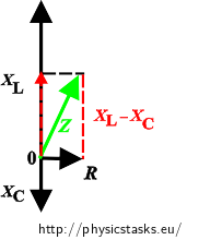
Remember what the formula for the total impedance of a series RLC circuit is and how it can be deduced from the phasor diagram of impedances.
Analysis
If the current flowing through the circuit is the same for both values of the capacitance of the capacitor, the Ohm’s law for an alternating current circuit implies that the circuit has the same impedance in both cases. We can express the inductance of the inductor that is connected in the circuit from this finding.
Knowing the inductance of the inductor we can easily calculate the current flowing through the circuit with given capacitance using the Ohm’s law for the alternating current circuit.
Solution
When it is stated that the current is the same for both capacitances of the condenser then also the total impedances of the circuit must be the same (the hint describes this in detail):
\[Z_1=Z_2. \]For the impedance of a series RLC circuit we can write:
\[\sqrt{R^2 + (X_L - X_{C1})^2}=\sqrt{R^2 + (X_L - X_{C2})^2},\]where R is the resistance of the resistor, XL is the inductive reactance of the inductor and XC is the capacitive reactance of the capacitor.
We substitute for the inductive reactance of the inductor and the capacitive reactances of the capacitor:
\[\sqrt{R^2 + (\omega L - \frac{1}{\omega C_1})^2}=\sqrt{R^2 + (\omega L - \frac{1}{\omega C_2})^2},\]where L is the inductance of the inductor and ω is angular frequency of the source voltage.
From this equality we stepwise express the inductance of the inductor Lwe are looking for. At first we raise both sides of the equation to the second power:
\[R^2 + (\omega L - \frac{1}{\omega C_1})^2=R^2 + (\omega L - \frac{1}{\omega C_2})^2,\] \[ (\omega L - \frac{1}{\omega C_1})^2= (\omega L - \frac{1}{\omega C_2})^2.\]Now we extract the square root of both sides of the equation:
\[ \omega L - \frac{1}{\omega C_1}= \pm (\omega L - \frac{1}{\omega C_2}).\]Square root gives us two possible equations:
\[ \omega L - \frac{1}{\omega C_1}= \omega L - \frac{1}{\omega C_2},\tag{1}\] \[ \omega L - \frac{1}{\omega C_1}= - \omega L + \frac{1}{\omega C_2}.\tag{2}\]If we take the first equation and solve it:
\[ \omega L - \frac{1}{\omega C_1}= \omega L - \frac{1}{\omega C_2}\quad\Rightarrow\quad \frac{1}{\omega C_1}= \frac{1}{\omega C_2}\quad\Rightarrow\quad C_1=C_2,\tag{1}\]it is obvious that this equality can never come true because the angular frequency of the source is fixed.
The second equation remains, from which we can express the inductance of the inductor L:
\[ \omega L - \frac{1}{\omega C_1}= - \omega L + \frac{1}{\omega C_2},\tag{2}\] \[ 2\omega L = \frac{1}{\omega C_1} + \frac{1}{\omega C_2} = \frac{1}{\omega }\left(\frac{1}{C_1} + \frac{1}{ C_2}\right),\] \[ L = \frac{1}{2 {\omega}^2 }\left(\frac{1}{C_1} + \frac{1}{ C_2}\right) = \frac{1}{2 (2\pi f)^2 }\frac{C_1+C_2}{C_1 C_2} = \frac{1}{8(\pi f)^2 }\frac{C_1+C_2}{C_1 C_2},\]where f is the frequency of the source voltage.
Knowing the inductance of the inductor we can already calculate the current flowing through the circuit with given capacitance C2. From the Ohm’s law it is valid:
\[ I = \frac{U}{Z_2},\]where I is the effective value of current and U is the effective value of voltage.
First we express the value of impedance Z2:
\[ Z_2 = \sqrt{R^2 + (\omega L - \frac{1}{\omega C_2})^2},\]and substitute the relation for inductance L that we have deduced above:
\[ L = \frac{1}{2 {\omega}^2 }\left(\frac{1}{C_1} + \frac{1}{ C_2}\right),\] \[ Z_2 = \sqrt{R^2 + (\frac{\omega}{2 {\omega}^2 }\left(\frac{1}{C_1} + \frac{1}{ C_2}\right) - \frac{1}{\omega C_2})^2}\]and solve:
\[ Z_2 = \sqrt{R^2 + (\frac{1}{2 {\omega} }\left(\frac{1}{C_1} + \frac{1}{ C_2}\right) - \frac{1}{\omega C_2})^2}= \] \[ = \sqrt{R^2 + (\frac{1}{2 {\omega} C_1 }+\frac{1}{2 {\omega} C_2 } - \frac{1}{\omega C_2})^2}= \sqrt{R^2 + (\frac{1}{2 {\omega} C_1 }- \frac{1}{2\omega C_2})^2}=\] \[=\sqrt{R^2 + (\frac{C_2-C_1}{2 {\omega} C_1 C_2})^2}=\sqrt{R^2 + (\frac{C_2-C_1}{4 \pi f C_1 C_2})^2}\]We substitute back into the Ohm’s law:
\[ I = \frac{U}{Z_2},\] \[ I =\frac{U}{\sqrt{R^2 + (\frac{C_2-C_1}{4 \pi f C_1 C_2})^2}}.\]Notation and numerical values
U = 10 V Effective value of the source voltage f = 50 Hz Frequency of the source voltage R = 5 Ω Resistance of the resistor C1 = 100 μF Capacitance of the capacitor C2 = 200 μF Capacitance of the capacitor L = ? Inductance of the inductor I = ? Effective value of current in the circuit for the capacitance of the capacitor set to C2
\[ L = \frac{1}{8(\pi f)^2 }\frac{C_1+C_2}{C_1 C_2}= \frac{1}{8(\pi\cdot 50)^2 }\frac{100{\cdot}10^{-6} +200{\cdot}10^{-6}}{100{\cdot}10^{-6} \cdot 200{\cdot}10^{-6} }\,\mathrm H \] \[ L \dot=0{,}76\,\mathrm H \]
\[ I =\frac{U}{\sqrt{R^2 + (\frac{C_2-C_1}{4 \pi f C_1 C_2})^2}} =\frac{10}{\sqrt{5^2 + (\frac{200{\cdot}10^{-6}-100{\cdot}10^{-6}}{4\cdot \pi \cdot 50 {\cdot} 100\cdot10^{-6} \cdot 200{\cdot}10^{-6}})^2}}\,\mathrm A \] \[ I \dot=1{,}06\,\mathrm A \]Answer
The inductance of the inductor is approximately 0,076 H. A current of approximately 1,06 A flows through the circuit if the capacitance is 200 μF.


