A single loop receding from a wire
Task number: 400
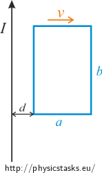
A solid metal loop (a single coil) with a width of 5 cm and a length of 10 cm recedes with velocity 4 m s-1 from a long straight wire with current 3 A. The velocity is perpendicular to the wire as shown in the diagram below. The loop stays in the same plane during its movement. Determine the magnitude of the induced voltage at the instant when the distance between the closer side of the loop and the wire is d = 2 cm.

Hint
Think of the equation for the voltage induced in a wire loop. What is the magnetic flux through the area of the wire loop?
Analysis
The voltage induced in a wire loop equals the negative change of the magnetic flux through the area of this wire loop per unit time.
The change of magnetic flux equals the difference between the initial and the final magnetic flux due to its small shift from its initial position.
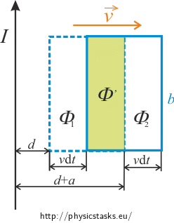
Let’s express the initial and final magnetic fluxes Φ1 and Φ2 as the sum of a magnetic flux Φ,, which is common to both and a magnetic flux dΦ1 or dΦ2 which is unique to each loop.
Picture

Remark: The shift of the loop is actually infinitesimally small. To make the picture more readable, the shift is shown much larger.
Solution
The voltage induced in a wire loop equals the negative change of the magnetic flux through the area of this wire loop per unit time.
\[U_i=-\frac{\mathrm{d} \Phi}{\mathrm{d}t}\tag{1}\]where dΦ is the change of the magnetic flux in time dt and can be replaced by the difference between the initial and the final magnetic flux
\[\mathrm{d}\Phi = \Phi_1 -\Phi_2\tag{2}\]Each magnetic flux could be expressed as the sum of a magnetic flux Φ,, which is common to both and a magnetic flux dΦ1 or dΦ2 which is unique to each wire loop.
\[\Phi_1 = \Phi^, + \mathrm{d}\Phi_{1}\tag{3}\] \[\Phi_2 = \Phi^, + \mathrm{d}\Phi_{2}\tag{4}\]It is clear that when calculating the change of the magnetic flux dΦ (eq. (2)) “the mutual flux” Φ, disappears. So, we need to express only the magnetic fluxes dΦ1 and dΦ2. Because the areas through which we measure the magnetic flux are infinitesimally small we can suppose that the magnetic field B does not change. Thus, we can use the general expression for magnetic flux
\[\Phi =BS\cos\alpha\tag{5}\]where α is the angle between the normal to an area and the magnetic field lines. In our case α = 0o and so cos α = 1.
The magnetic field B can be expressed by the equation for a magnetic field surrounding a long straight wire.
\[B=\frac{\mu_o}{2\pi}\frac{I}{d}\tag{6}\]S is the area through which we measure the magnetic flux. In our case the areas dΦ1 and dΦ2 have the same value (see figure).
\[S = b v \mathrm{d}t\tag{7}\]Now we can recast the equations for Φ1 and Φ2 [using equations ((5)-(6)-(7))] as
\[\Phi_1 = \Phi^, + \,\frac{\mu_o}{2\pi}\frac{I}{d}\,b\,v\,\mathrm{d}t\tag{8}\] \[\Phi_2 = \Phi^, + \,\frac{\mu_o}{2\pi}\frac{I}{d+a}\,b\,v\,\mathrm{d}t\tag{9}\]The change in the magnetic flux equals [using equations (2), (8), (9)]
\[\mathrm{d}\Phi = {\mu_o Ibv\mathrm{d}t}{2\pi} (\frac{1}{d}-\frac {1}{d+a})\tag{10}\]Now we can express the induced voltage using equations (1) and (10) as
\[U_i = {\mu_o Ibv\mathrm{d}t}{2\pi \mathrm{d}t} (\frac{1}{d}-\frac {1}{d+a})\]After mathematical simplification we get
\[U_i = {\mu_o Ibv}{2\pi}\, \frac{a}{d(d+a)}\]Numerical solution
\[v=4 \,\mathrm{ms^{-1}}\] \[a = 5\,\mathrm{cm}=0.05 \,\mathrm{m}\] \[b=10\,\mathrm{cm}=0.10 \,\mathrm{m} \] \[d = 2\,\mathrm{cm}=0.02 \,\mathrm{m}\] \[I = 3\,\mathrm{A}\] \[U_i = ?\]
\[|U_i| = {\mu_o Ibv}{2\pi}\, \frac{a}{d(d+a)}= \frac{4\cdot \pi \cdot 10^{-7} \cdot3{\cdot}0.1{\cdot} 4}{2\pi}\,\cdot \frac{0.05}{0.02\cdot(0.02+0.05)}\,\mathrm{V}\] \[|U_i|=8.6\,\mathrm{\mu V}\]Answer
The induced voltage in the wire loop during its movement (at the given distance d) is Ui = 8.6 μV.
Comment – Solution using total magnetic flux through a wire loop
The magnetic flux through an area of a wire loop is defined as
\[\Phi=\int{\vec{B}\cdot\,\mathrm{d}\vec{S}}\]Because the vector of the magnetic field is perpendicular to the area of the wire loop, we can rewrite the integral as
\[\Phi=\int{B}\,\mathrm{d}S\]The magnetic field B can be expressed by the equation for the magnetic field surrounding a long straight wire at a distance x from a wire.
\[B = \frac{\mu_o I}{2\pi x}\]The distance x is a variable. An element of the area dS can be expressed as dS=bdx.
The range of distances from the wire, which we will use as the bounds of integration, are the distances of both sides of the loop from the wire. The magnetic flux can be expressed as
\[\Phi=\int_d^{d+a}{\frac{\mu_o}{2\pi}\,\frac{I}{x}\,b\,\mathrm{d}x}\]The constants can be moved out of the integral
\[\Phi=\frac{\mu_oIb}{2\pi}\,\int_d^{d+a}{\frac{1}{x}}\,\mathrm{d}x\]After an easy integration we get
\[\Phi=\frac{\mu_oIb}{2\pi}\,\left[\mathrm{ln}\,x \right]_d^{d+a}=\frac{\mu_oIb}{2\pi}\, \mathrm{ln}\frac{d+a}{d}\]The task is to determine the induced voltage. The voltage can be expressed as the time derivative of the magnetic flux
\[U_i = -\frac{\mathrm{d}\Phi}{\mathrm{d}t}\] \[U_i = -\frac{\mathrm{d}}{\mathrm{d}t}\left(\frac{\mu_oIb}{2\pi}\, \mathrm{ln}\frac{d+a}{d}\right)\]The only time dependent variable is d. Because the velocity is constant, we can express the distance as
\[d(t)=vt\]Let’s now insert the distance into the equation for induced voltage
\[U_i = -\frac{\mu_oIb}{2\pi}\,\frac{\mathrm{d}}{\mathrm{d}t}\left(\mathrm{ln}\frac{vt+a}{vt}\right)\]After taking the derivative
\[U_i = -\frac{\mu_oIb}{2\pi}\,\frac{vt}{vt+a}\,\frac{-av}{(vt)^{2}}\]which can be rewritten as
\[U_i = \frac{\mu_oIb}{2\pi}\,\frac{1}{vt+a}\,\frac{a}{t}\]Let’s input the moment when the loop reaches the required distance, i.e. \(t =\frac{d}{v}\)
\[U_i = \frac{\mu_oIb}{2\pi}\,\frac{1}{d+a}\,\frac{av}{d}\] \[U_i = \frac{\mu_oIb}{2\pi}\,\frac{av}{d(d+a)}\]The equation for the induced voltage determined using the other procedure has the same form as above.


