Shunt and ballast resistor
Task number: 2167
Milliammeter meter with range up to 15 mA has internal resistance of Rm = 5 Ω. How is a resistor required to be connected to the device and what resistance does it have to have to allow us to measure with the device:
a) currents up to 0.15 A?
b) voltage up to 150 V?
Hint 1
For us not to damage the device, we have to add resistance to the circuit so that the current running through the device won’t exceed 15 mA.Hint 2
Voltmeter and ammeter do not differ in construction but do differ in the way you connect them to a circuit and in internal resistance. According to Ohm’s law, current is directly proportional to voltage.
Analysis
First, let’s revise the basics of connecting resistors:
If we connect two resistors into a series circuit then the same current will run through both resistors and the total voltage will be equal to the sum of voltages at each resistor.
If we connect two resistors into a parallel circuit then the current will split into the two branches of the circuit and voltage will be the same on both resistors. Also, the inverse value of the total resistance equals the sum of inverse values of each resistor’s resistance.
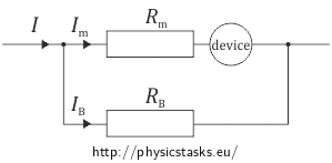
a) If we need to measure current of higher value than our measuring devices allow, we will connect a resistor with appropriate resistance into a parallel circuit. This resistor is called a shunt. The total current running through the circuit will be equal to the sum of currents running through the measuring device and the shunt.

b) First think about how to find out the allowable voltage on our measuring device.
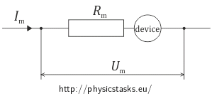
Allowable voltage is the maximum voltage that will not damage our measuring device. Its value can be calculated from the Ohm’s law - the internal resistance of the device multiplied by the maximal allowable current.
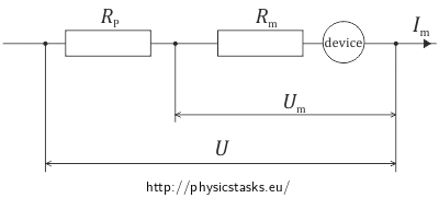
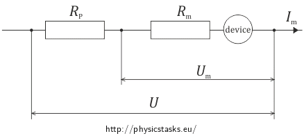
For measuring voltage higher than allowable voltage on the measuring device, we will connect a resistor to the device in a series circuit. This resistor is called a ballast resistor. The total measured voltage will be equal to the sum of voltages on the device and the ballast resistor.

Solution of part a)
We need the total current I that is running through the circuit to be higher than the current through the milliammeter Im, for that we will connect a resistor in parallel to the device (so called shunt).

These apply because we have connected a resistor into a parallel circuit:
\[U_B\,=\,U_m\,=\,R_mI_m\] \[I\,=\,I_m+I_B\,. \]We know from Ohm’s law that:
\[R_B\,=\, \frac{U_B}{I_B}\,.\]Putting everything into the equation, we get the relation for the shunt’s resistance:
\[R_B\,=\, \frac{R_m I_m}{I-I_m}\,. \]Solution of part b)
We need the total voltage to be 150 V.
Allowable voltage of the device can be calculated using allowable current:
\[U_m\,=\,R_mI_m\,=\,5{\cdot} 0{,}015\,\mathrm{V}\,=\,0{,}075\,\mathrm{V}\,.\]The total voltage that we want to measure is higher than the allowable voltage of the measuring device. That is why we will connect a resistor to the device in series (so-called ballast resistor).

The resistor was connected in series, so we can apply the following for its voltage and current:
\[U_P\,=\,U - U_m\,=\,U - R_mI_m\] \[I_P\,=\,I_m\,. \]Ohm’s law says that:
\[R_P\,=\, \frac{U_P}{I_P}\,.\]And after putting everything together, we get:
\[R_P\,=\, \frac{U - R_m I_m}{I_m}\] \[R_P\,=\, \frac{U}{I_m} - R_m\,. \]List of known information and substitution
\(I_{m}\,=\,15\,\mathrm{mA}\,=\,0{,}015\,\mathrm{A}\) the maximal value of current at the milliammeter \(R_m\,=\,5\,\mathrm{\Omega}\) the miliammeter’s resistance \(I\,=\,0{,}15\,\mathrm{A}\) the current that we want to measure with the milliammeter \(U\,=\,150\,\mathrm{V}\) the total measured voltage \(R_B\,=\,?\,\mathrm{(\Omega)}\) the shunt’s resistance \(R_P\,=\,?\,\mathrm{(\Omega)}\) the ballast resistor’s resistance
\[R_B\,=\, \frac{R_m I_m}{I-I_m}\,=\, \frac{5}{9}\,\mathrm{\Omega}\,\dot{=}\,0{,}56\, \mathrm{\Omega}\] \[R_P\,=\, \frac{U}{I_m}-R_m\,=\,9\,995\,\mathrm{\Omega}\,\dot{=}\,10\,000\,\mathrm{\Omega}\]Answer
To measure current of up to 0.15 A, we must connect a resistor with resistance of approximately 0.56 Ω in parallel to the device.
To measure voltage of up to 150 V, we must connect a resistor with resistance of approximately 10 000 Ω in series to the device.


