Conducting Rails
Task number: 1538
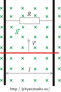
Two long, parallel and perfectly conducting rails at a distance 50 cm from each other are placed in a homogeneous magnetic field with magnetic induction 2 mT, which is perpendicular to the rail plane. The rails are conductively connected at one point. Electrical resistance of the connection is 5 Ω. A perfectly conducting rod slides on these rails with a constant speed 2 ms-1. Determine:
a) electromotive force induced in the conducting rod, the value and direction of induced electric current in the closed part of the circuit,
b) mechanical pulling force needed to keep the rod at the constant speed and mechanical power.

Note: When solving this task, we neglect the mechanical effects such as friction etc.
Hint
Under what circumstances is electromotive force induced in a conducting loop and how is it related to the flux of magnetic induction?
If electric current flows in a conductor located in a magnetic field, a magnetic force acts on the conductor. Its direction is determined by Fleming's left-hand rule. Does this force accelerate or decelerate the movement of the conductor?
Fleming's left-hand rule
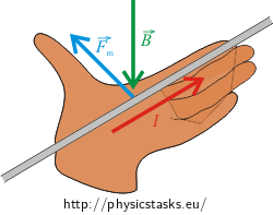
If we put our left hand on the conductor in such a way that the outstretched fingers point in the direction of the current flow and magnetic lines of induction (or vector \(\vec{B}\)) point into our palm, the thumb indicates the direction and orientation of the vector of magnetic force \(\vec{F}_m\), which acts on the conductor.

Analysis
The conductively connected rails and the conducting rod form a loop. Electromotive force is induced in this loop, as long as the magnetic flux through this loop changes. We can imagine the flux as a "number of lines of induction passing through the loop area". It is very important that the induced EMF does not depend on the total "number of induction lines" passing through the loop area, but only on the "change of their number". More precisely speaking, the size of the induced EMF - and therefore the size of electric current - depends on the rate of change of magnetic flux inside the loop area.
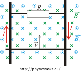
By moving the conductive rod upwards (see figure) we decrease the loop area and thus the magnetic flux through the loop area. Electric current is induced in the circuit and a magnetic field around the circuit is generated. The magnetic lines of induction of this field are of such direction that to prevent the change in the magnetic flux, i.e. the direction is such that it increases the magnetic flux. The direction of the lines inside the loop is therefore the same as the direction of the external magnetic field, i.e. away from us (parallel with the plane of the picture). We can determine the direction of induced current using Ampere’s rule. The current flows in the clockwise direction. The size of electric current can be determined from Ohm's law.
Magnetic force acts on a conductor with electric current moving in a magnetic field. The direction of this force is determined by Fleming's left-hand rule. The direction of this force is exactly opposite to the direction of the vector of velocity, i.e. the magnetic force slows the movement of the conductor down. This could be seen directly from the fact that this force acts against the cause of the generation of electric current, i.e. counteracts the movement of the conductor. To maintain a constant speed of the moving conductor, another force of the opposite direction must act on the conductor. In our case it is mechanical force, which is of the same size as the magnetic force, but of the opposite direction.
The mechanical power is determined from the definition of mechanical power – it is work performed by the force divided by time per which the work was performed.
Solution of a)
Determining the induced electromotive force
The induced electromotive force is equal to the change of magnetic flux Φ through the surface area of the loop per time Δt
\[U_i=-\frac{\mathrm{\Delta} \Phi}{\mathrm{\Delta}t}.\tag{1}\]For the induction flux it applies
\[\Phi =B S\,cos \alpha,\]where α is the angle between the normal vector of the surface of the loop, and the induction lines, in our case α = 0°, i.e. cos α = 1. Because the vector of magnetic induction B is of a constant magnitude, the change of the induction flux ΔΦ can be determined as follows
\[\mathrm{\Delta}\Phi = B\mathrm{\Delta}S,\]where ΔS is a change of the surface area and it is equal to
\[\mathrm{\Delta}S= - lv \mathrm{\Delta}t.\]The minus sign results from the fact that the area of the loop decreases.
The expression for the change of magnetic flux is substituted into equation (1) for induced electromotive force Ui
\[U_i=-\frac{-Blv \mathrm{\Delta}t}{\mathrm{\Delta}t}= Blv \,\frac{\mathrm{\Delta}t}{\mathrm{\Delta}t}= Blv.\]Evaluation of the size and direction of induced current
We determine the size of electric current induced in the loop from Ohm's law, where the voltage U is the electromotive force Ui and the resistance R is the resistance of the conducting wire connecting the rails (the rails are ideally conducting, which means that their resistance can be neglected, as well as the resistance of the moving connecting rod)
\[U_i=R I \,\,\,\Rightarrow\,\,\,I=\frac{U_i}{R}.\]By substituting the induced electromotive force Ui into this equation we obtain the size of the induced current
\[I=\frac{Blv}{R}.\tag{2}\]The direction of the induced electric current is determined by using the Ampere's rule. The thumb points in the direction of the induction lines of magnetic field generated by the conductor with current. According to Lenz's law the vector \(\vec{B}_i\) of the field within the loop is of the same direction as the vector \(\vec{B}\) of the external magnetic field; this is to compensate the reduction of magnetic flux through the loop. Curved fingers then show the direction of the current in the conductor. The figure shows that the current flows in a clockwise direction.

Note: The external magnetic field is drawn in green; the magnetic field of the loop is represented by blue.
Solution of b)
Evaluation of mechanical force
Magnetic force acts on a conductor with current placed in a magnetic field. The magnitude of this force is
\[F_m=BIl sin\alpha,\]where the angle α is the angle between the vector of magnetic induction and the current direction. In our case, the vector of magnetic induction is perpendicular to the conductor with the current and thus the angle is α = 90° and magnetic force Fm is given by
\[F_m=BIl.\]We determine the direction of this force by using Fleming's left-hand rule. The direction of this force is opposite to the direction of the velocity, i.e. the magnetic force slows the moving conductor down. To maintain a constant speed, another force of the opposite direction must act on the moving conductor. In our case it is the mechanical force \(\vec{F}\), which is of the same size as the magnetic force \(\vec{F}_m\), but has an opposite direction, i.e. the following applies:
\[F=F_m=BIl.\]We substitute the relation (2), which we have evaluated in the previous section, for I
\[I=\frac{Blv}{R}.\]The magnitude of mechanic force thence is
\[F=\frac{B^2l^2v}{R}.\tag{3}\]Evaluation of power of mechanical force
Power P is defined as work W done per time t
\[P=\frac{\mathrm{\Delta}W}{\mathrm{\Delta}t}.\]We can express the work W as a force F acting on a body and moving it a displacement Δs
\[P=\frac{F\mathrm{\Delta}s}{\mathrm{\Delta}t}.\]Velocity v is defined as change of displacement per time, that is \(\frac{\mathrm{\Delta}s}{\mathrm{\Delta}t}\). Power P can be expressed as
\[P=Fv,\]We substitute the formula(3) for the force \(\vec{F}\) and we obtain the power of mechanical force:
\[P=\frac{(Blv)^2}{R}.\]Given values and numerical substitution
\[l = 50\,\mathrm{cm}=0.50\,\mathrm{m}\] \[R=5\,\mathrm{\Omega}\] \[B=2{\cdot}10^{-3}\,\mathrm{T}\] \[v=2\,\mathrm{ms^{-1}}\] \[U_i=?\] \[I=? \] \[F=? \] \[P=? \]
\[|U_i|=Blv=2{\cdot}10^{-3}\cdot0.5{\cdot}2\,\mathrm{V}=2{\cdot}10^{-3}\,\mathrm{V}=2\,\mathrm{mV}\] \[I=\frac{Blv}{R}=\frac{2{\cdot}10^{-3}\cdot0.5{\cdot}2}{5}\,\mathrm{A}=0.4{\cdot}10^{-3}\,\mathrm{A}=0.4\,\mathrm{mA}\] \[F=\frac{B^2l^2v}{R}=\frac{(2{\cdot}10^{-3})^2{\cdot}0.50^2{\cdot}2}{5}\,\mathrm{N}=4{\cdot}10^{-7}\,\mathrm{N}=0.4\,\mathrm{\mu N}\] \[P=\frac{(Blv)^2}{R}=\frac{(2{\cdot}10^{-3}\cdot0.50{\cdot}2)^2}{5}\,\mathrm{W}=8{\cdot}10^{-7}\,\mathrm{W}=0.8\,\mathrm{\mu W}\]Odpověď
Electromotive force Ui = 2 mV is generated in a rod sliding on conducting rails. The electric current induced in the loop is I = 0.4 mA and it flows in the clockwise direction.
To maintain the given speed of the rod, a force F = 0.4 μN must act on the rod. The power of this force is P = 0.8 μW.


