Real Inductor
Task number: 1789
We connect a real inductor to a source of alternating voltage with an effective value of 10 V and a frequency of 50 Hz. A current with an effective value of 16 mA flows through this circuit. The current drops to 12 mA when we connect a resistor with a resistance of 470 Ω in series with the inductor. Assess the inductance L and the resistance RL of the inductor.
Hint – real inductor
A real inductor has both an inductance and a resistance. We draw a real inductor as an ideal inductor connected in series to an ideal resistor in a circuit diagram.

Hint
The assignment describes two circuits — first, we connect only the real inductor to the source; second, we connect the real inductor and the resistor in series to the source. We are to assess two unknowns — the inductance and the resistance of the inductor. Try to use Ohm’s law for each of the two alternating current circuit and thus get a system of two equations for two unknowns.
Hint – series connection of inductor and resistor
Attaching the resistor to the inductor changes the total resitance Rtotal of the circuit. In the series circuit, the resistatnces of individual elements sum up:
\[ R_\mathrm{total} = R_L + R. \]Analysis
We use Ohm’s law for alternating circuits to write down the equations for the voltages in the two circuits — one with the inductor only and the other with the inductor and the resistor. We derive the total impedances of the two circuits using impedance diagrams. In this way we get a system of two equations with two unknows — the inductance and the resistance of the inductor. We obtain the values of the unknowns by solving this system of equations.
Solution
The real inductor is connected in alternating current circuits. This means that it is characterized both by the inductance L and the resistance RL.
In the first case (without the additional resistor), Ohm’s law is
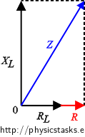
\[ V = Z_L I_1, \]where V is the effective voltage of the source, ZL is the impedance of the real inductor and I1 is the effective current flowing through the circuit in the first case. We assess the impedance of the real inductor ZL from the following diagram:
\[ Z_L = \sqrt{ R_L^2 + X_L^2}, \]
where XL is the inductive reactance of the inductor; and we substitute into Ohm’s law above:
\[ V = \sqrt{ R_L^2 + X_L^2}\, I_1. \]
In the second case, we connect the resistor in series with resistance R to the real inductor. Ohm’s law for this alternating circuit is:
\[ V = Z I_2, \]where Z is the total impedance of the circuit and I2 is the effective current flowing through the second circuit. We assess the total impedance of the second circuit from the following diagram.
\[ Z = \sqrt{ (R+R_L)^2 + X_L^2 }\]
and we substitute into Ohm’s law for this circuit:
\[ V = \sqrt{ (R+R_L)^2 + X_L^2 }\, I_2. \]
We obtained a system of two equations for two unknown quantities — the inductive reactance XL and resistance RL of the inductor:
\[ V = \sqrt{ R_L^2 + X_L^2}\, I_1, \tag{1}\] \[ V = \sqrt{ (R+R_L)^2 + X_L^2 }\, I_2. \tag{2}\]We arrange the equations and raise them to the second power:
\[ \frac{V}{I_1} = \sqrt{ R_L^2 + X_L^2} \hspace{60px}\Rightarrow\qquad\left(\frac{V}{I_1}\right)^2 = R_L^2 + X_L^2, \] \[ \frac{V}{I_2} = \sqrt{ (R+R_L)^2 + X_L^2 }\qquad\Rightarrow\qquad \left(\frac{V}{I_2}\right)^2 = (R+R_L)^2 + X_L^2 . \]By subtracting the equations, we get one equation with one unknown — the resistance RL because the inductive reactances XL subtract:
\[ \left(\frac{V}{I_1}\right)^2-\left(\frac{V}{I_2}\right)^2 = R_L^2 + X_L^2 - [ (R+R_L)^2 + X_L^2 ]. \]We rearrange the equation:
\[ \left(\frac{V}{I_1}\right)^2-\left(\frac{V}{I_2}\right)^2 = - R^2 -2R R_L \]and get the resistance of the inductor RL:
\[ R_L= \frac{- R^2 - \left(\frac{V}{I_1}\right)^2+\left(\frac{V}{I_2}\right)^2 }{2R} = \frac{V^2}{2RI_2^2} \,-\,\frac{R}{2} \,-\, \frac{V^2}{2RI_1^2}.\]
We express the inductive reactance of the inductor XL from one of the equations:
\[ V = \sqrt{ R_L^2 + X_L^2}\, I_1, \tag{1}\] \[ \frac{V}{I_1} = \sqrt{ R_L^2 + X_L^2}, \] \[ \left(\frac{V}{I_1}\right)^2 = R_L^2 + X_L^2, \] \[ X_L = \sqrt{\left(\frac{V}{I_1}\right)^2 - R_L^2}. \]And we substitute the above derived expression for the resistance of the inducor RL:
\[ X_L = \sqrt{\left(\frac{V}{I_1}\right)^2 - \left(\frac{V^2}{2RI_2^2} \,-\,\frac{R}{2} \,-\, \frac{V^2}{2RI_1^2}\right)^2}. \]We use the knowledge that the relation between the inductance and the inductive reactance is XL = 2πfL, where f is the source frequency:
\[ 2 \pi f L = \sqrt{\left(\frac{V}{I_1}\right)^2 - \left(\frac{V^2}{2RI_2^2} \,-\,\frac{R}{2} \,-\, \frac{V^2}{2RI_1^2}\right)^2 }, \] \[ L = \frac{1}{ 2 \pi f} \sqrt{\left(\frac{V}{I_1}\right)^2 - \left(\frac{V^2}{2RI_2^2} \,-\,\frac{R}{2} \,-\, \frac{V^2}{2RI_1^2}\right)^2 }. \]Notation and numeric substitution
V = 10 V Effective value of the source voltage I1 = 16 mA = 0,016 A Effective current through the first circuit R = 470 Ω Resistance of the resistor I2 = 12 mA = 0,012 A Effective current through the second circuit f = 50 Hz Frequency of the source voltage RL = ? (Ω) Resistance of the real inductor L = ? [H] Inductance of the real inductor
\[ R_L=\frac{V^2}{2RI_2^2} \,-\,\frac{R}{2} \,-\, \frac{V^2}{2RI_1^2}= \frac{10^2}{2{\cdot} 470 \cdot 0{,}012^2} \,-\,\frac{470}{2} \,-\, \frac{10^2}{2{\cdot} 470 \cdot 0{,}016^2}\,\dot=\, 88 \,\mathrm \Omega \] \[ L = \frac{1}{ 2 \pi f}\sqrt{\left(\frac{V}{I_1}\right)^2 - \left(\frac{V^2}{2RI_2^2} \,-\,\frac{R}{2} \,-\, \frac{V^2}{2RI_1^2}\right)^2 } =\] \[ \,\ \ = \frac{1}{ 2 \cdot \pi \cdot 50}\sqrt{\left(\frac{10}{0{,}016}\right)^2 - \left(\frac{10^2}{2{\cdot} 470 \cdot 0{,}012^2} \,-\,\frac{470}{2} \,-\, \frac{10^2}{2{\cdot} 470 \cdot 0{,}016 ^2}\right)^2 } \,\dot=\,2\,\mathrm H \]Answer
The resistance of the inductor is approximately 88 Ω and its inductance is about 2 H.


