Parallel RLC Circuit
Task number: 1787
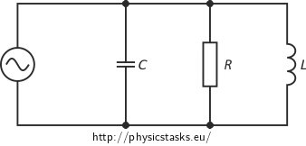
A resistor, an ideal capacitor and an ideal inductor are connected in parallel to a source of alternating voltage of 160 V at a frequency of 250 Hz. A current of 2 A flows through the resistor and a current of 0.8 A flows through the inductor. The total current through the circuit is 2.5 A. Assess the resistance of the resistor, the capacity of the ideal capacitor and the inductance of the ideal inductor (presume that IC > IL).
Note: The assigned values of voltage and currents are the effective values.
Hint — circuit diagram

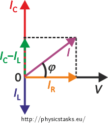
Hint — phasor diagram
A phasor diagram for a parallel alternating current circuit is drawn analogically to that for a series circuit. We must take into account that in a parallel circuit, the voltage is the same across all elements, in contrast to a series circuit, where the same current flows through all elements.
How to draw the phasor diagram of a parallel RLC circuit: Draw the phasor of voltage along the x axis as well as the phasor of current through the resistor. Draw the phasor of the current through the capacitor along the positive direction of the y axis and the phasor of the current through the inductor along the negative direction of the y axis.
Notation
V = 160 V Source voltage f = 250 Hz Frequency of the source voltage IR = 2 A Current through the resistor IL = 0.8 A Current through the inductor I = 2.5 A Total current through the circuit R = ? [Ω] Resistance of the resistor C = ? [F] Capacity of the capacitor L = ? [H] Inductance of the inductor Analysis
We find the unknown quantities using Ohm’s law for alternating current circuits that we apply to each element. The voltage across all elements is equal to the source voltage because we deal with a parallel circuit.
We find the unknown current through the capacitor using the assigned currents and the phasor diagram for the parallel RLC circuit.
Solution and numerical substitution
Resistance R of the resistor:
The circuit is parallel and the voltage across the resistor VR is thus the same as the source voltage V. Thence, we can write Ohm’s law for the alternating current circuit in the form:
\[ V = I_\mathrm R R, \]where IR is the effective value of current flowing through the resistor. We express the resistance of the resistor R from the equation:
\[ R = \frac{V}{I_\mathrm R}. \]And we use the assigned values:
\[ R = \frac{160}{2}\,\mathrm \Omega = 80\,\mathrm \Omega. \]
Inductance L of the inductor:
The voltage across the inductor VL is again the same as the source voltage V and we can express it from Ohm’s law for the alternating current circuit:
\[ V = X_\mathrm L I_\mathrm L = 2 \pi f L\, I_\mathrm L, \]where XL is the inductive reactance of the inductor, f is the source voltage frequency, L is the inductance of the inductor and IL is the effective value of current flowing through the inductor.
We express the inductance L:
\[ L = \frac{V}{2 \pi f I_\mathrm L}, \]and we use the assigned values:
\[ L = \frac{160}{2 \cdot \pi \cdot 250 {\cdot} 0.8}\,\mathrm H \,\dot=\, 0.13 \,\mathrm H. \]
Capacity C of the capacitor:
We derive the capacity of the capacitor C also from Ohm’s law for the alternating current circuit:
\[ V = X_\mathrm C I_\mathrm C =\frac{I_\mathrm C}{2 \pi f C},\]where XC is the capacitive reactance of the capacitor, f is the source voltage frequency, and IC is the effective current through the capacitor. The voltage across the capacitor is the same as the source voltage V.
We express the capacity of the capacitor C:
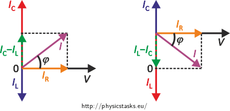
\[ C =\frac{I_\mathrm C}{2 \pi f V}.\tag{1}\]We draw the phasor diagram for currents in order to calculate the effective current IC flowing through the capacitor, taking into account that the assignment states that IC > IL:

We express the relation between the currents from the phasor diagram:
\[ I^2 = (I_\mathrm C - I_\mathrm L)^2 + I_\mathrm R^2. \]We multiply out and rearrange:
\[ I^2 = I_\mathrm C^2 - 2I_\mathrm L I_\mathrm C +I_\mathrm L^2 + I_\mathrm R^2, \] \[ 0 = I_\mathrm C^2 - 2I_\mathrm L I_\mathrm C +(I_\mathrm L^2 + I_\mathrm R^2 - I^2).\]We solve the quadratic equation for the unknown current IC:
\[(I_\mathrm C)_\mathrm {1{,}2} = \frac{ 2 I_\mathrm L \pm \sqrt{ (2 I_\mathrm L)^2 - 4 (I_\mathrm L^2 + I_\mathrm R^2 -I^2)}}{2}. \]We rearrange:
\[(I_\mathrm C)_\mathrm {1{,}2} = I_\mathrm L \pm \sqrt{ ( I_\mathrm L)^2 - (I_\mathrm L^2 + I_\mathrm R^2 -I^2)}, \] \[(I_\mathrm C)_\mathrm {1{,}2} = I_\mathrm L \pm \sqrt{ I^2 - I_\mathrm R^2 }. \]And we use the assigned values:
\[(I_\mathrm C)_\mathrm {1} = 0.8 + \sqrt{ 2.5^2 - 2^2 }\,\mathrm A= 2.3 \,\mathrm A ,\] \[(I_\mathrm C)_\mathrm {2} = 0.8 - \sqrt{ 2.5^2 - 2^2 }\,\mathrm A= -0.7\,\mathrm A .\]Only the positive value of the effective current IC = 2.3 A is physically meaningful in our case.
We substitute this result into the equation for the capacity of the capacitor (1) that we derived above from Ohm’s law:
\[ C =\frac{I_\mathrm C}{2 \pi f U}= \frac{2.3}{2 \cdot \pi \cdot 250 {\cdot} 160}\,\mathrm F \,\dot=\, 9.2 {\cdot} 10^{-6} \,\mathrm F = 9.2 \,\mathrm{ \mu F}. \]Answer
The resistor has a resistance of 80 Ω, the inductor has an inductance of approximately 0.13 H and the capacity of the capacitor is about 9.2 μF.


