Induction without a Conductor
Task number: 1530
A time-varying unifrom field \(\vec{B}(t)\) pointing straight upwards fills a cylinder of a radius R. In time, only the magnitude of magnetic field varies. Describe the electric field generated inside the cylinder.
Hint 1
Use the Maxwell equation expressing Faraday’s law in integral form
\[\oint_c \vec E\cdot d\vec l = -\frac{d\Phi}{dt},\]the integral on the left side of the equation (corresponding to the induced voltage) is calculated over a closed contour C in space, and the component on the right side of the equation expresses a time variation of induction flux through the surface of the contour.
Hint 2
The question is how to choose the contour properly, so that the integral in Maxwell’s equations (see previous hint) can be calculated “simply”.
For this purpose prove that the vector of electric intensity rotates around the cylinder axis (similarly the vector of magnetic induction rotates around a thin straight wire with current) and that that the magnitude of electric intensity depends only on the distance from the cylinder axis.
A suitable contour is therefore a circular loop encircling the cylinder axis.
Express also the time derivative of induction flux using a surface area of the contour and a time derivative of the magnetic induction.
Analysis
According to Faraday’s law of electromagnetic induction, a variable magnetic field induces an electric field. This law is generally used in tasks where the loop is formed by a conductor. In this task, it is important to note that the presence of the conductor is not essential. The induced electric field is generated all the same.
To calculate the electric field we can use Faraday’s law, but this time we use the form including the electric field intensity. This form is actually one of the Maxwell’s equations in integral form
\[\oint_c \vec E\cdot d\vec l = -\frac{d\Phi}{dt}.\]The left side of the equation can be integrated over any closed contour c. To calculate this integral, we need to choose this contour conveniently. Due to the cylindrical symmetry the convenient choice appears to be a circle with its centre on the axis of the cylinder lying in its perpendicular section: the vector of electric field intensity must be perpendicular to the vector of magnetic induction at all points (this results from Maxwell’s equations directly and applies to every electromagnetic field), thus it must lie in the plane of the normal section of the cylinder.
It is also true that the electric field intensity vector has equal magnitude at any point of the circle, and its direction is tangent to the circle at that point; for detailed justification see section Solution.
In this case, the integral on the left and the change of induction flux can be easily determined.
Solution – Faraday’s law
We use the integral form of Faraday’s law, which states that
\[\oint_c \vec{E}\cdot {\rm d}\vec l = -\frac{{\rm d}\Phi}{{\rm d}t}.\tag{1}\]On the left there is actually an electromotive force generated in an arbitrary closed contour c. It does not matter, whether this curve represents a real conductor; the electric field is generated nevertheless! In a coil conductor the generated electric field is demonstrated by an induced current.
Thus we can arbitrarily choose a closed contour along which we integrate the left side. A suitable choice of the curve c is a circle (of radius r < R) lying in a perpendicular section of cylinder with its centre on the cylinder axis. The vector of electric field intensity \(\vec{E}\) lies in the circle plane (it must be perpendicular to the \(\vec{B}\) vector). Then, regarding the symmetry of the situation, we can see that the vector is tangent to the circle at every point of the circle.
This deserves a more detailed comment. It can be explained in several ways; here, however, we try to avoid using differential operators and offer a physical view instead. The cylindrical symmetry of the situation guarantees us one thing: If the vector \(\vec{E}\) was deflected from the tangent, it would be "equally defected" from the tangent at all points of the circle. Then we could decompose the intensity vector into two components: a component tangent to the circle and a normal component. Due to the symmetry a normal component is zero and the vector of electric intensity \(\vec{E}\) is tangent to the circle.
If the normal component were not zero, we could imagine a conductor in the direction of the normal component, this component of electric field intensity would cause a current flow and a magnetic field circulating around the conductor would be generated. It is not essential for a conductor to physically be there – an electric field generates a magnetic field, there is no need of a conductor. Such a magnetic field, however, is not present, according to the assignment of this task.
Let us summarize what we know from the symmetry: the electric field intensity vector is tangent to the circle at all points of the circle and of the same magnitude E. The integral on the left side of the equation (1)) is thus equal to
\[\oint_c \vec E\cdot {\rm d}\vec l = \oint_c E\,{\rm d}l = E \oint_c {\rm d}l = E \ (2\pi r).\]On the right side of the equation (1) there is a time derivative of induction flux through the area S designated by the circle. Due to \(\vec{B}\) and \(\vec{S}\) vectors being parallel and the area of the circle being constant, we can write
\[-\frac{{\rm d}\Phi}{{\rm d}t} = -S\frac{{\rm d}B}{{\rm d}t} = -\pi r^2\frac{{\rm d}B}{{\rm d}t}\]By comparing with the result of the left side of the equation (1) we obtain:
\[E\cdot (2\pi r) = -\pi r^2\frac{{\rm d}B}{{\rm d}t}\] \[E = -\frac{r}{2}\frac{{\rm d}B}{{\rm d}t}\]The minus sign indicates the fact that the induced field is trying to prevent the change that caused it. So it is associated with the direction, not the size of the electric intensity vector.
Solution – Orientation of induced field
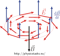
We have already stated that the direction of electric field intensity is tangent to the circle. What is its orientation? Suppose the magnetic field increases. The field on the circle must then circulate in such a direction that a current flow in an imaginary current loop generates a magnetic field in the centre of the loop pointing downward.
According to Ampere's right hand rule the intensity "circulates" the circle in the clockwise direction.

It is necessary to point out that the blue arrows in the picture above do not show the magnetic induction \(\vec{B}\), but its time derivative! The magnetic induction \(\vec{B}\) induced by the electric field is represented with the black vector. The blue vector pointing upwards therefore indicates that the magnetic field increases (according to the assignment the magnetic field inside the cylinder points upward). The red arrows then represent the electric field intensity vector \(\vec{E}\) at certain points.
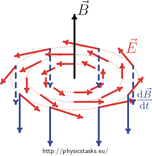
To be exact, we must add that if the magnetic field weakened, then the "blue" vector of time derivative of the magnetic field would be pointing downward, and the vector of electric field intensity would be circulating around the cylinder axis in the opposite direction, i.e. counter clockwise. The magnetic induction \(\vec B\) induced by the electric field is again represented with a black vector. (See below.)

Answer
If the magnetic induction increases, the vector of electric field intensity rotates around the axis in a clockwise direction.
If the magnetic induction decreases, the vector of electric field intensity rotates around the axis in a counter clockwise direction.
In both cases the size of the electric intensity vector is proportional to the distance r from the axis of rotation:
\[E = \frac{r}{2}\frac{{\rm d}B}{{\rm d}t}\]


