Two Parallel Conductors Carrying Current
Task number: 1779
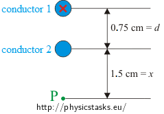
Two very long parallel conductors are located at a distance of 0.75 cm from each other, perpendicular to the plane of the figure below. Conductor 1 is carrying a current of 6.5 A towards the picture plane. What current (magnitude and direction) must flow through conductor 2 to produce a zero magnetic field at point P?

Hint
Realize, what magnetic field does a straight conductor carrying a current produce.
What must be the orientation of the magnetic B‑field of the two conductors to produce a zero magnetic field at the point P?
Analysis
Since the conductors carry electric currents, they make magnetic fields around them. The magnetic B‑field is the largest in the vicinity of the conductor; the further we are from it, the smaller the magnetic field is.
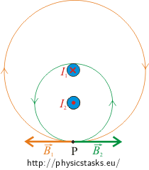
Magnetic field is depicted by magnetic field lines. The tangents to these oriented lines point in the direction of the magnetic B‑field in the given point. The orientation of the field line is determined by the north pole of a compass. The magnetic field lines form concentric circles in the vicinity of the conductor with their centers located in the center of the conductor. The orientation depends on the direction of the current that is carried by the conductor. If the current flows towards us from the picture plane, the field lines are oriented counterclockwise according to Ampère’s right hand screw rule, and vice versa.
The B‑field at point P should be zero in our case. It follows that the B‑field of the conductor 1 must have opposite orientation to the B‑field of conductor 2. The current in conductor 2 thus has to flow in the other direction than the current in conductor 1, i.e. towards us.
The magnitudes of the B‑fields must be equal to produce a zero total field. From this fact we assess the magnitude of the current in the second conductor.

Solution
It was pointed out already in the analysis that the B‑fields of both conductors must have the same magnitude and opposite orientations at the point P to produce a zero total field there. This means that the current in conductor 2 must flow towards us. The two contributions are equal in magnitude:
\[B_1=B_2\]The magnitude of the B‑field in distace r from a straight conductor carrying current I is given as
\[B\,=\,\mu_0 \frac{I}{2\pi r}\]where μ0 is the permeability of vacuum.
The distance between the point P and the conductor 2 is labelled \(x\) in the Figure.
\[B_2=\mu_0\frac{I_2}{2\pi x}\]The distance between the point P and the conductor 2 is equal to the sum \(d + x\).
\[B_1= \mu_0\frac{I_1}{2\pi(d+x)}\]The magnitudes of the B‑fields are to be equal.
\[\mu_0\frac{I_1}{2\pi(d+x)}=\mu_0\frac{I_2}{2\pi x}\]And we express the unknown current I2.
\[I_2=I_1\frac{x}{d+x}\]Notation and numerical substitution
\(x\,=\,1.5\,\mathrm{cm}\) distance between point P and the nearer conductor (2) \(d\,=\,0.75\,\mathrm{cm}\) distance between the conductors \(I_1 \,=\,6.5\,\mathrm{A}\) current flowing through the first conductor \(I_2\,=\,?\,\mathrm{(A)}\) current flowing through the second conductor There is no need to convert distances from centimeters to meters because the length dimensions stand in a plain ratio in the numerator and the denominator of the fraction. Their units thus cancel out.
\[I_2=I_1\frac{x}{d+x}=6.5\frac{1.5}{0.75+1.5}\,\mathrm{A}=4.3\,\mathrm{A}\]Answer
The current through the conductor 2 has a magnitude of
\[I_2=4.3\,\mathrm{A}\]and it flows in the opposite direction than the current in conductor 1, which means that it flows towards us.


