Series RLC Circuit
Task number: 1540
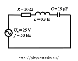
An AC circuit is composed of a serial connection of:

Given values
We write down the quantities given in the assignment:
Resistance of resistor R = 50 Ω Inductance of the coil L = 0.3 H Capacitance C = 15 μF =15·10-6 F Amplitude of AC voltage source Um = 25 V Frequency of source f = 50 Hz Resistor, coil and capacitor are connected in series.Quantities that we want to determine:
Amplitude of the current in the circuit Im = ? (A) Phase difference between the voltage and the current in the circuit φ = ? (°) Task analysis
How to solve this task:
- We evaluate the current amplitude. We apply Ohm's law for the alternating current, which expresses the relationship between an overall impedance Z, a voltage amplitude of the source Um and a current amplitude Im. For this calculation, we know all the quantities from assignment.
- Electric current flowing through all the components connected in series is of the same size; however the voltage on the components is out of phase with the current. To obtain the phase difference (shift) between voltage and current we use a phasor diagram.
How to draw a phasor diagram
A phasor is an "arrow" that we use to plot the current and voltage values on individual components of the circuit into a phasor diagram. Its magnitude reflects the amplitude of the voltage or current, and its direction indicates the phase angle.
Drawing a phasor diagram for a series circuit:
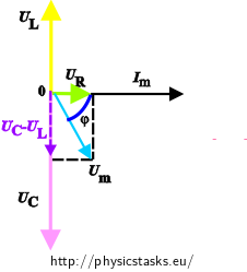
We plot the values of voltage and current on individual components in the AC circuit into the phasor diagram.- The current is of the same size on all the components, the phasor of current Im is therefore the same for all the components and is usually drawn in the positive direction of the x-axis.
- The phasor of voltage is on the resistor UR parallel to the current phasor, because the phase difference between the voltage and current is zero – in this case voltage and current are in phase. In the figure the phasor is illustrated by green.
- The voltage on the coil UL leads the current by π/2 (quarter of a period), therefore we draw its phasor pointing upwards – in the positive direction of the imaginary y-axis. We consider the fact that the phasors rotate in a counter clockwise direction. In the figure, this phasor is represented by yellow.
- The current on the capacitor leads the voltage UC by π/2. Therefore we draw the phasor pointing downward – that is in negative direction of the y-axis. This phasor is represented by pink.
- The amplitude of the overall voltage is obtained by a "vector sum" of phasors of the voltage on individual components. First, we subtract the voltage on the capacitor UC from the voltage on the coil UL (in the picture drawn in purple). Then we add this vector and the vector of the voltage on the resistor UR. The phasor of the voltage amplitude of the entire circuit is represented by light blue.
- A phase difference between the voltage and the current is said to be the angle φ between the current phasor and the overall voltage phasor. The angle φ is drawn by navy blue
For an RLC circuit and the given quantities the phasor diagram looks like this:

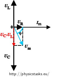
In the following figures the phasor diagrams are not illustrated by the same colours.
Derivation of the formula for total impedance Z from the phasor diagram
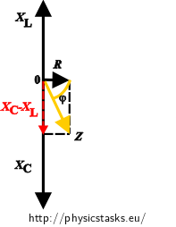
To get the total impedance Z from the phasor diagram, instead of the voltage on individual components in the phasor diagram we plot the inductance XL, the capacitance XC and the resistance R.
From Ohm's law we know that:
\( U_C=I_m X_C\mathrm{,}\hspace{20px}U_L=I_m X_L\mathrm{,}\hspace{20px} U_R=I_m R\mathrm{.} \)Since the current through all the components is the same, the impedances of individual elements are proportional to the voltage, so we can draw a diagram similar to the voltage phasors.

To calculate the impedance Z we use the rectangular triangle we can see in the phasor diagram. The impedance Z is evaluated by using Pythagorean theorem.
\[ Z^2=R^2+(X_C-X_L)^2 \]or:
\[ Z^2=R^2+(X_L-X_C)^2 .\]The difference between the relationships is whether the current leads voltage or the voltage leads the current. The size of the impedance Z is however not affected
By substituting the relations of inductance and capacitance we obtain:
\[ Z= \sqrt{R^2+(X_L-X_C)^2}= \sqrt{R^2+\left({ \omega L- \frac{1}{\omega C}}\right)^2} \]Evaluating amplitude of electric current
The formula for expressing the impedances Z from Ohm's law is:
\[ Z=\frac{U_m}{I_m}=\sqrt{R^2+(\omega L-\frac{1}{\omega C})^2} \]
We determine the amplitude of the current Im. We can easily derive
\[ I_m=\frac{U_m} {\sqrt{R^2+\left(\omega L-\frac{1}{\omega C}\right)^2}} \]from the previous formula.
Evaluating phase difference from the phasor diagram


The phase shift is expressed from the phasor diagram usually in the form:
\[ \mathrm{tg\,} \varphi = \frac{U_L-U_C}{U_R} =\frac{I_m\omega L- \frac{I_m}{\omega C}}{I_mR}=\frac{\omega L-\frac{1}{\omega C}}{R}= \frac{X_L-X_C}{R}\mathrm{.} \]When we draw a phasor diagram and a phase difference, the formula
\[ \mathrm{tg\,} \varphi = \frac{U_L-U_C}{U_R}= \frac{X_L-X_C}{R} \]can be replaced by the formula
\[ \mathrm{tg\,} \varphi = \frac{U_C-U_L}{U_R}= \frac{X_C-X_L}{R}\mathrm{.} \]We must be careful in interpreting the results. In the first case the numerator says that we consider the case when the voltage leads the current (similarly as on the coil). In the second case, on the other hand, the current leads the voltage. We choose a suitable relationship either from the phasor diagram, where we can see the phase difference between the voltage and current, or we choose one of the relations and interpret the result through the sign of the resulting value. If you choose, for example, the second formula for expressing the phase difference and the resulting value has a plus sign, then the current leads the voltage. However, if the resulting value of the phase difference is negative, then the voltage leads the current.
Numerical substitution
The current amplitude:
\[ I_m= \frac{U_m}{\sqrt{R^2+\left(\omega L-\frac{1}{\omega C}\right)^2}}= \] \[ = \frac{25}{\sqrt {50^2+\left({2\pi \cdot 50 {\cdot} 0{.}3 - \frac{1}{2 \pi \cdot 50 {\cdot} 15 \cdot 10^{-6}}}\right)^2}}\,\mathrm{A} \,\dot{=}\, 0.2\,\mathrm{A} \]We can evaluate the phase difference by the impedance:
\[ \mathrm{tg\,} \varphi = \frac{ \omega L- \frac{1}{ \omega C}}{R} = \frac{ 2 \pi \cdot 50 {\cdot} 0.3- \frac{1}{ 2 \pi \cdot 50 {\cdot} 15 \cdot 10^{-6} }}{50} \,\dot{=}\,-2{.}4 \]Or it can be evaluated by using the voltage on individual components in the circuit:
The voltage on individual components of the circuit is:
\[ U_R=I_mR\,\dot{=}\,0{.}2 {\cdot} 50\,\mathrm{V}=10\,\mathrm{V}\] \[U_L=I_m \omega L\,\dot{=}\, 0{.}2 {\cdot} 2 \pi \cdot 50 {\cdot} 0{.}3\,\mathrm{V}\dot= 18{.}85\,\mathrm{V}\] \[U_C=\frac{I_m}{\omega C}\,\dot{=}\,\frac{0{.}2}{2 \pi \cdot 50 {\cdot} 15 \cdot 10^{-6}}\,\mathrm{V}\dot= 42{.}44\,\mathrm{V} \]We determine the size of the phase difference between the voltage and the current in the circuit from the phase diagram:
\[ \mathrm{tg\,} \varphi=\frac{U_L-U_C}{U_R}\dot= \frac{18{.}85-42{.}44}{10}\dot= -2{.}4 \]Both methods gave us the same result:
\[ \varphi\, \dot{=} \, -67 ^\circ \]A negative value says that the current leads the voltage.
Answer
In the series RLC circuit the amplitude of the current is approximately:
Im = 0.2 A.The phase difference between the voltage and the current is about:
φ = -67°.ZThe sign of the phase difference means that the current leads the voltage by about 67° (since the current leads the voltage, this circuit acts as a capacitor).


