Galvanometer
Task number: 401
The rectangular coil of a galvanometer has fifty turns. The side perpendicalar to the rotating axis is 3.0 cm long; the second side (parallel to the rotating axis) is 2.0 cm long. The coil is placed in a radial magnetic field of 0.010 T.
The torsion coefficient of the hair spring on which the coil hangs is
1.0·10-8N·m·rad-1.
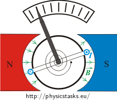
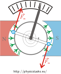
- Draw a diagram of the magnetic forces acting on the sides of the coil parallel to the rotation axis. The direction of the current is marked.
- Determine the deviation of the galvanometer’s hand if the current through the coil is 1.0 mA.
- Discuss what would happen if the current through the coil changed its direction.
Hint
If a coil with a current is placed in a magnetic field, magnetic forces will act on its sides. The orientation of those forces could be determined using Fleming’s left hand rule.
Magnetic forces acting on the sides of a coil cause the coil to start to rotate. Thanks to the spring, the hand connected to the coil will stop at some angle and will not rotate further. In an equilibrium state the moment of magnetic force equals the moment of force by which the spring acts on the coil. In other words, at equilibrium the two torques must be equal and opposite.
Hint – A torsion moment and a torsion coefficient
A torsion pendulum (see the picture) is another example of an object undergoing oscillatory motion. If we turn the disc of a torsion pendulum from its equilibrium state by a small angle and then release it, a mark (a line) on it will oscillate about its equilibrium position – this is called a torsion oscillation. A reversible torsion moment of force, or torque, of a twisted fibre is created at all non-equilibrium positions with a deflection φ in either direction. The magnitude of such a torsion moment could expressed as
\[M=-\kappa \varphi,\]where κ is the torsion constant. The torsion constant depends on the length of the fibre, its diameter and the material the fibre is made of.
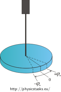
The action of the spring on the galvanometer’s hand can be characterized in the same way as the acting of a fibre on a disc. The torsion constant of a spring is the constant of proportionality between the magnitude of the spring’s moment of force and the angle of the hand’s deflection.
Analysis
The measurement of a current in a galvanometer using a movable coil is based upon the torque created by the magnetic field on a loop with current.
In the galvanometer there is a coil on a core made of soft ferromagnetic material between permanent magnets. The shape of the permanent magnets is such that the magnetic field between them has a radial character (see the picture in the assignment).
If there is a current in a coil placed in such a magnetic field, there will be a pair of magnetic forces acting on the coil and turning both the coil and a hand attached to it. To avoid rotation and keep its hand at some angle, a spring is attached to the coil. This spring creates a moment of force equal and opposite to the moment of magnetic force acting on the coil. The moment of force by which a spring acts is proportional to its deflection from an equilibrium state.
The direction of both magnetic forces and the rotation of the coil
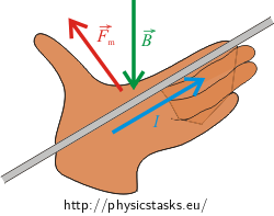
The direction of the magnetic forces acting on the coil with current can be found using Fleming’s left hand rule, which says that:
If we lay our open left hand on a wire so the pointed fingers represent the direction of the current in the wire and the magnetic field vector \(\vec{B}\) (or flux lines) aims into the open hand, the thumb represents the direction of the magnetic force \(\vec{F}_{\textrm{m}}\), which acts on the wire.
There is a pair of magnetic forces acting on a coil with a current placed in a magnetic field. These two forces cause a deflection of the coil counter clockwise, i.e. the galvanometer’s hand deflects leftwards.
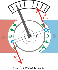
Remark: There is no force acting on the sides of the coil. This is because these wires are parallel to the magnetic field vector \(\vec{B}\).
If the galvanometer is plugged into a circuit conversely, the current through the galvanometer has the opposite direction and the galvanometer’s hand deflects rightwards.
From the considerations above it is clear that alternating current evokes a pair of forces with alternating directions. In such situation a galvanometer’s hand does not settle but oscillates with the same frequency as the current. If the frequency is too high the hand can not follow the current (because of the inertia due to its mass) and stays in the position corresponding to zero current through the coil (in the centre of the galvanometer scale).
Solution
If there is a current in a coil placed in such a magnetic field, there will be a pair of magnetic forces acting on the coil and turning both the coil and a hand attached to it. To avoid rotation and keep its hand at some angle a spring is attached to the coil. This spring creates a moment of force equal and opposite to the moment of magnetic force acting on the coil. The moment of force by which the spring acts is proportional to its deflection from an equilibrium state. This means the deflection of the coil is proportional to the current through it.
Let’s express the equality of the moment of a magnetic force M and the moment of the spring’s force M’ mathematically
\[M=M’.\]To express the magnitude of the moment of a magnetic force M we should know the forces evoking this moment.
Let’s determine the magnetic forces acting on the sides of the wire loop using
\[F_m=I\vec{l}\times\vec{B}=IlB\sin\alpha,\]where the angle α is between the magnetic field vector \(\vec{B}\) and the direction of the current through the wire.
Magnetic forces acting on the coil’s sides perpendicular to the rotation axis of the coil.
Thanks to the radial magnetic field between the permanent magnets, the magnetic field vector is always parallel to the current at the sides of the coil and so there are no magnetic forces acting on these sides.
Magnetic forces acting on the coil’s sides parallel to the rotation axis of the coil
The angle made by the direction of the current through the part of the coil parallel to the rotation axis and the magnetic field vector is α = 90o. The magnitude of the magnetic force acting on such a wire with length b is
\[F_1=F_2=IbB\sin 90^o=IbB.\]Forces \(\vec{F}_1,\,\vec{F}_2\) are parallel and have opposite directions.
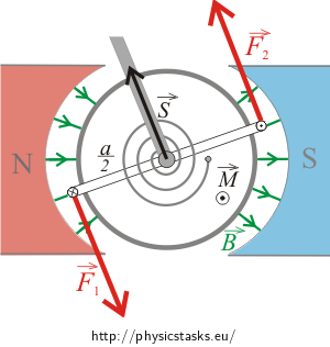
The moments of both forces are in the same direction, they are perpendicular to a plane made by both forces and their sum is
\[M=F_1\frac{a}{2}+F_2\frac{a}{2}=\frac{a}{2} (F_1+F_2) .\]Because forces F1 and F2 have the same magnitude, we can rewrite the equation as
\[M=\frac{a}{2} (F_1+F_2)=F_1 a=IabB=ISB .\]where S = ab is the area of the coil. The total moment of forces acting on a coil with N loops is
\[M=NISB \]The magnitude of the moment of the spring’s force M’ can be expressed as
\[M'=\kappa \varphi,\]where κ is the torsion constant and φ is the angular deflection.
From above we know these two moments are equal (M=M’) so we write
\[NISB=\kappa \varphi.\]and from this the deflection φ can be expressed as
\[\varphi=\frac{NISB}{\kappa}.\]Numerical solution
\[Z=50\] \[a=3.0\,\mathrm{cm}=0.030\,\mathrm{m}\] \[b=2.0\,\mathrm{cm}=0.020\,\mathrm{m}\] \[B=0.010\,\mathrm{T}\] \[k=1.0{\cdot} 10^{-8}\,\mathrm{Nm/^o}\] \[I=1.0\,\mathrm{mA}=1{\cdot} 10^{-3}\,\mathrm{A}\] \[\varphi=?\]
\[\varphi=\frac{NISB}{k}=\frac{50{\cdot} 10^{-3}\cdot0.03{\cdot}0.02{\cdot}0.01}{1.0{\cdot} 10^{-8}}=30^o\]Answer
The deflection of the galvanometer with current 1.0 mA is φ = 30o.
If the galvanometer is plugged into a circuit conversely, the current through the galvanometer has the opposite direction and the galvanometer’s hand deflects the other way.


