Capacitor with Plate on a Spring
Task number: 3250
Air capacitor consists of two parallel horizontal plates with area of S = 100 cm2. The lower plate is fixed, the upper plate is hanging on a spring with stiffness of k = 1 N m−1. The spring allows movement up and down (the plates remain parallel. We connect a voltage source to the plates which we will use to increase the voltage between them. With zero voltage, the plate distance is d = 2 mm. The plates will near each other with increasing voltage.
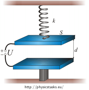
a) Derive the relation between voltage U and shift x of the upper plate in which the attractive force of the plates and the spring force are in equilibrium from the original position of the upper plate.
b) Draw the graph of the dependence of shift x on voltage U.
c) Discuss which equilibria are stable and which are unstable.
d) What is the maximum voltage for which the plates are in stabile equilibrium? What is the distance between the plates for this voltage?
a) Hint 1
If the plate is at rest, the resulting force acting on it must be zero. Note what forces act on the plate.a) Hint 2
How will these forces change if we connect the plates to a changeable voltage?
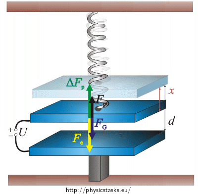
Picture of Acting Forces
a) Analysis
The gravitational force and the spring force act on the upper plate of the capacitor if not under voltage. The spring force tries to pull the plate upwards to return the spring into its original state. Since the plate is at rest, the resulting force must be zero.
If we connect the plate to a voltage source, electric force starts to act on the plates of the capacitor pulling them together. The upper plate starts to move downwards which strains the spring and the spring force will increase. If the plates are at rest again, the change in spring force is equal to the electric force (the force resultant is zero).
We will find the voltage from the equality of the electric force and the spring force difference.
a) Solution: Voltage and Shift Relation Derivation
If the voltage between the two plates of the capacitor is zero, then only the gravitational and spring forces act on the upper plate of the capacitor. The plate is at rest so the resultant of these two forces must be zero.
If we connect the plates to a source of voltage, the plates will begin to approach each other because of electric force \(\vec{F}_e\). The upper plate will move downwards. This will cause the spring to be more strained and the more it is strained the more it pulls back.
The spring force will increase by:
\[\mathrm{\Delta} F_p\,=\,kx\,,\tag{1}\]where k is the stiffness of the spring and x is the shift of the upper plate.
Now we express the size of electric force Fe which acts on the upper plate if the capacitor. The following applies for the force:
\[F_e\,=\,Q \frac{E}{2}\,,\tag{*}\]where \(\frac{E}{2}\) is the size of the electric field intensity which is created by the bottom plate. The derivation of this fact can be found in more detail in the task Force Acting on Capacitor Plates.
Electric field intensity E between the the plates depends on voltage U and plate distance l:
\[E\,=\,\frac{U}{l}\,.\]With zero voltage, the plates are d apart. If we connect the plates to a voltage source, the upper plate will move. Distance between the plates d will decrease by shift x and the final distance of the plates will be: l = d − x.
The following then applies for the electric field intensity between the two plates:
\[E\,=\,\frac{U}{d-x}\,.\]We will substitute this relation into the equation for the electric force (*)
\[F_e \,=\, Q\frac{E}{2}\,=\,Q\frac{U}{2\left(d-x\right)}\,.\]The charge on a capacitor plate is directly proportional to the voltage and capacity of the capacitor: \(Q=CU\)
\[ F_e\,=\,\frac{CU^2}{2\left(d-x\right)}\,.\tag{**}\]Now we express the capacity which is dependent on the area of the plates of the capacitor S, vacuum permittivity ε0 and distance between the two plates d − x using the following relation:
\[C\,=\,\frac{\varepsilon_0 S}{l}\,=\,\frac{\varepsilon_0 S}{d-x}\]We substitute the capacity into the relation for the electric force (**)
\[F_e\,=\,\frac{\varepsilon_0 S U^2}{2\left(d-x\right)^2}\,.\tag{2}\]We have obtained a relation for the electric force which acts on the upper plate.
We are interested in the state in which the attractive electric force is equal to the spring force difference:
\[F_e\,=\,\mathrm{\Delta}F_p\,.\]We substitute the relation for the electric force (2) and the spring force increase (1).
\[\frac{\varepsilon_0 S U^2}{2\left(d-x\right)^2}\,=\,kx\]We want to express the relation between voltage U and shift x. We adjust the relation so that we are left with voltage U on the left hand side of the equation only.
We multiply the equation by \(\frac{2\left(d-x\right)^2}{\varepsilon_0 S }\)
\[U^2\,=\,\frac{2kx\left(d-x\right)^2}{\varepsilon_0 S }\]and we make the square root:
\[U\,=\,\sqrt{\frac{2kx\left(d-x\right)^2}{\varepsilon_0 S }}\,.\tag{***}\]We have obtained the dependence of voltage U on upper plate shift x.
b) Hint: Voltage Dependence on Plate Shift Graph
We have expressed voltage U dependence on plate shift x in part a).
\(U\,=\,\sqrt{\frac{2kx\left(d-x\right)^2}{\varepsilon_0 S }}\)Our task is to draw the opposite dependence into a graph. Shift x cannot be simply expressed from this relation though.
Try to utilize the relation between a graph of a function and the graph of the inverse function.
b) Solution: Shift Dependence on Voltage
Voltage depends on shift according to equation (***) which was derived in the previous section.
\[U\,=\,\sqrt{\frac{2kx\left(d-x\right)^2}{\varepsilon_0 S }}\]Our task is to draw the graph showing the dependence of shift on voltage. Expressing shift x is too complicated (x can be found in the equation to the first, second and third power at the same time). We do not need to express x to draw the graph of the dependence. All we need to do is to notice that the expression of x is the inverse function to the expression of U.
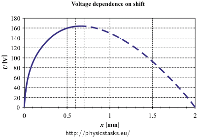
First we draw the dependence of voltage on shift. We have it expressed already. Then we will flip the graph with respect to the axis of the first quadrant. (We swap the axes of voltage and shift.)
To draw the graph of voltage dependence on shift, we substitute the given values into relation (***):
\[S\,=\,100\,\mathrm{cm^2}\,=\,0.01\,\mathrm{m^2}\] \[k\,=\,1\,\mathrm{Nm^{-1}}\] \[d\,=\,2\,\mathrm{mm}\,=\,2{\cdot}10^{-3}\,\mathrm{m}\] \[\varepsilon_0\,=\,8.85{\cdot} 10^{-12}\,\mathrm{ C^2\,N^{-1}\,m^{-2}}\]We obtain the following dependence:
\[U\,=\,\sqrt{\frac{2 \cdot x \cdot \left(2{\cdot}10^{-3}-x\right)^2}{8{,}85{\cdot} 10^{-12}\cdot 0{,}01 }}\]We process the graph using a handy table editor (MS Excel for example) for shift x values from 0 mm (when plates are at distance d) to 2 mm (the distance between plates is zero).
Now we can draw the graph we search for. Beware of the dashed part. The function is not injective and so there is no inverse function to it in the whole interval \( \langle 0\,;2 \rangle \). Because of this, we draw only the growing part of the function, from 0 to the maximum.
Here you can download an MS Excel file with the graphs.
c) Hint
Think about how the sizes of the electric force and the spring force change for a set voltage with altering plate distance.
Draw a graph of this dependence and use it to explain stability and instability of equilibrium states.
c) Analysis and Solution
To find out the reason behind the plates not being able to stay in any stable equilibrium state, we need to look closer at the graph of voltage dependence on the equilibrium state of the upper plate (see graph in the section of solution b). At first the function is ascending, i.e. I have to connect the plates to a higher voltage if I want a bigger shift. For a particular shift the voltage reaches its maximum and then it declines as the shift increases. Thus we have two equilibrium states for one voltage. Only in the case of maximal voltage there is only one equilibrium state.
We need to find out if these two equilibrium states are stable or unstable. We will draw a graph of electric force and spring force dependence on the position of the upper plate with a set constant voltage.
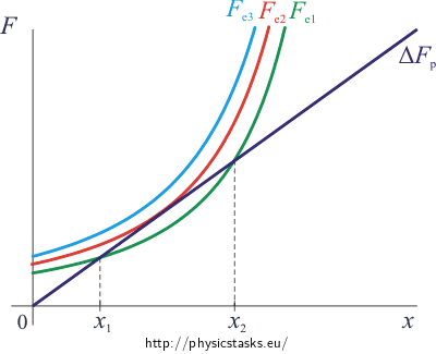
The graph of spring force increment ΔFp dependence on shift x
\[\mathrm{\Delta}F_p\,=\,kx\]is a line intersecting the origin (coloured purple in the graph). Since the size of this force does not depend on the voltage, it is constant for all voltages.
The graph of electric force size Fe dependence on shift x
\[F_e\,=\,\frac{\varepsilon_0 S U^2}{2 \left(d-x\right)^2}\]is a curve that looks similarly to one branch of the hyperbola. The shape and the position of this curve depend on voltage.
The curve and the line have one common point for the maximal voltage (coloured red in the graph). The curve and the line have two common points for voltages lower than the maximum (one such case is green in the graph). The curve and the line have no common points for voltages higher than the maximum (coloured blue in the graph).
Now we can discuss the stability and instability of equilibria.
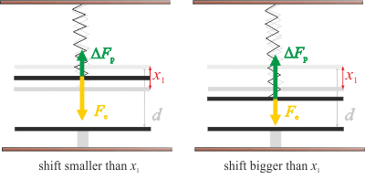
We will look at the green curve and its intersection point with the line first. In this case the plate will stabilize in distance x1. If we shift the plate farther from the bottom plate (the left side from the intersection), the electric force will overpower the spring force and the plate will return to the equilibrium state. If we shift the plate closer to the bottom plate (the right side from the intersection), the electric force will become smaller than the spring force and the spring pulls the plate back to the equilibrium state. Both situations are shown in the pictures bellow. This equilibrium is stable.
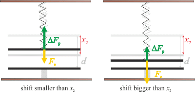
We will look at the second intersection now. In this case the plate will stabilize in distance x2. If we shift the upper plate farther away from the bottom plate, the spring force overpowers the electric force and the plate will move upwards away from the equilibrium. If we shift the upper plate closer to the bottom plate, the electric force overpowers the spring force and the upper plate will be pulled towards the bottom one. See picture bellow. This equilibrium state is called unstable.
The boundary between the stable and unstabile equilibria is the state in which the capacitor is connected to the maximum voltage. The size of the electric force for maximum voltage is drawn red in the graph above. In this case there is only one distance in which the plates are in equilibrium. The electric force will overpower the spring force in every other position and it will pull the plate down.
In practice it will look like this: With increasing voltage, the plates will move closer to each other while staying in stable equilibrium. Once we overtake the maximum voltage, the electric force will overpower the spring force and the plates clap together.
d) Hint
The boundary between the stable and the unstable equilibria is the position of the plate in which the voltage is the highest and the plates are in equilibrium.
The function extreme (minimum or maximum) is located at stationary points or at points where there are no first derivatives. Stationary points can be found by setting the first derivative of the function equal to zero \(\frac{\mathrm{d} f}{\mathrm{d} x} \, =\,0\).
d) Solution: Maximal Voltage for Stable Equilibrium
The boundary of stable equilibrium is the maximum of the curve. If we look at the graph (or into the table of values), we can guess the maximum first. It is about 160 V. The voltage is maximal when the upper plate is shifted by something between 0.6 mm and 0.7 mm. We can find the exact value if we find the maximum of the function.
The function extreme (minimum or maximum) is located at stationary points or at points where there are no first derivatives. Stationary points can be found by setting the first derivative of the function equal to zero \(\frac{\mathrm{d} f}{\mathrm{d} x} \, =\,0\).
We will adjust the relation first so that it is easier to differentiate. We factor all constants out and we partially square root:
\[ \frac{\mathrm{d}U}{\mathrm{d}x}\,=\,\frac{\mathrm{d}}{\mathrm{d}x} \sqrt{\frac{2kx\left(d-x\right)^2}{\varepsilon_0 S }}\,=\,\frac{\mathrm{d}}{\mathrm{d}x} \sqrt{\frac{2k}{\varepsilon_0 S }}\sqrt{x}\left(d-x\right)\,.\]Constant \(\sqrt{\frac{2k}{\varepsilon_0 S }}\) can be factored out of the derivative
\[ \frac{\mathrm{d}U}{\mathrm{d}x}\,=\,\sqrt{\frac{2k}{\varepsilon_0 S }}\,\frac{\mathrm{d}}{\mathrm{d}x} \sqrt{x}\left(d-x\right)\,.\]We differentiate the product
\[ \frac{\mathrm{d}U}{\mathrm{d}x}\,=\,\sqrt{\frac{2k}{\varepsilon_0 S }}\, \left(\frac{\mathrm{d}\sqrt{x}}{\mathrm{d}x} \left(d-x\right)+\sqrt{x}\frac{\mathrm{d}\left(d-x\right)}{\mathrm{d}x} \right)\,,\] \[\frac{\mathrm{d}U}{\mathrm{d}x}\,=\,\sqrt{\frac{2k}{\varepsilon_0 S }}\, \left(\frac{1}{2\sqrt{x}} \left(d-x\right)-\sqrt{x} \right)\,.\]Now we put the derivative equal to zero:
\[ \sqrt{\frac{2k}{\varepsilon_0 S }}\, \left(\frac{1}{2\sqrt{x}} \left(d-x\right)-\sqrt{x} \right)\,=\,0\]We eliminate the constant and adjust the equation to express shift x:
\[ \frac{1}{2\sqrt{x}} \left(d-x\right)-\sqrt{x}\,=\,0\] \[ \frac{1}{2\sqrt{x}} \left(d-x\right)\,=\,\sqrt{x} \hspace{20px}|\cdot 2\sqrt{x}\] \[ d-x\,=\,2x\hspace{20px}|\cdot +x\] \[ d\,=\,3x\hspace{20px}| \cdot \frac{1}{3}\] \[ x\,=\,\frac{d}{3}\]For this value of x, the voltage is maximal. Its value can be calculated by substituting \( x\,=\,\frac{d}{3}\) into relation (***):
\[U\,=\,\sqrt{\frac{2kx\left(d-x\right)^2}{\varepsilon_0 S }} \] \[U_{\mathrm{max}}\,=\,\sqrt{\frac{2k\frac{d}{3}\left(d-\frac{d}{3}\right)^2}{\varepsilon_0 S }}\,=\,\sqrt{\frac{2k\frac{d}{3}\left(\frac{2d}{3}\right)^2}{\varepsilon_0 S }} \]We partially square root:
\[U_{\mathrm{max}}\,=\,\frac{2d}{3}\sqrt{\frac{2k\frac{d}{3}}{\varepsilon_0 S }}\,=\,\frac{2d}{3}\sqrt{\frac{2kd}{3\varepsilon_0 S }} \]We have obtained the final relation for maximal voltage calculation where the plates are still in stable equilibrium.
\[U_{\mathrm{max}}\,=\,\frac{2d}{3}\sqrt{\frac{2kd}{3\varepsilon_0 S }} \]d) List of Known Information and Numerical Calculation
\[S\,=\,100\,\mathrm{cm^2}\,=\,0.01\,\mathrm{m^2}\] \[k\,=\,1\,\mathrm{Nm^{-1}}\] \[d\,=\,2\,\mathrm{mm}\,=\,2{\cdot}10^{-3}\,\mathrm{m}\]Constants found in tables:
\[\varepsilon_0\,=\,8.85{\cdot} 10^{-12}\,\mathrm{ C^2\,N^{-1}\,m^{-2}}\]
\[x_{\mathrm{max}}\,=\,\frac{d}{3}\,=\,\frac{2{\cdot}10^{-3}}{3}\,\dot=\,6.7 {\cdot}10^{-4}\,\mathrm{m}\,\dot=\,0.67\, \mathrm{mm}\] \[U_{\mathrm{max}}\,=\,\frac{2d}{3}\sqrt{\frac{2kd}{3\varepsilon_0 S }} \,=\,\frac{2{\cdot} 2\cdot10^{-3}}{3}\sqrt{\frac{2 {\cdot} 2\cdot 10^{-3}}{3{\cdot} 8.85 {\cdot} 10^{-12} \cdot 0.01}}\] \[U_{\mathrm{max}}\, \dot= \, 164\, \mathrm{V}\]Answer
a) Voltage depends on shift according to relation: \(U\,=\,\sqrt{\frac{2kx\left(d-x\right)^2}{\varepsilon_0 S }}\).
b)
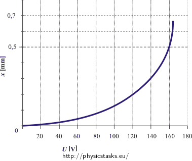
c) The plates are in stable equilibrium for small voltages. With rising voltage, the stable position of the plate moves downward. Aside from the stable equilibrium, there is also the unstable equilibrium for the same voltage range. The unstable position of the plate is closer to the bottom plate than the stable position. Once the voltage rises to its maximal value, the plates join because there is no equilibrium for voltages this high. It does not exist because the electric force overpowers the spring force at every point in which the plate can be.
d) The boundary voltage for stable equilibrium existence is:
\[U_{\mathrm{max}}\,=\,\frac{2d}{3}\sqrt{\frac{2kd}{3\varepsilon_0 S }}\, \dot{=} \, 164\, \mathrm{V}\] \[x_{\mathrm{max}}\,=\,\frac{d}{3}\,\dot=\,0.67\, \mathrm{mm}\]List of Derivatives
The list of derivatives used in solution of d) is in this section:
\[\frac {\mathrm{d} \left(c \cdot f\right)}{\mathrm{d}x} \,=\, c \cdot \frac {\mathrm{d}f}{\mathrm{d}x}\] \[\frac {\mathrm{d} \sqrt{x}}{\mathrm{d}x} \,=\, \frac {1}{2\sqrt{x}}\] \[\frac {\mathrm{d} \left(c - x\right)}{\mathrm{d}x} \,=\,-1\,,\]where c is a constant and f is a function.
Product derivative
\[\frac {\mathrm{d} \left( f \cdot g \right)}{\mathrm{d}x} \,=\, \frac {\mathrm{d} f }{\mathrm{d}x}\cdot g \,+\,f \cdot\frac {\mathrm{d} g }{\mathrm{d}x},\]where f and g are functions.
