Resonance Frequency of Combined Series-Parallel Circuit
Task number: 1166
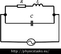
Assess the resonance frequency of the RLC circuit connected according to the picture.

Hint – resonance circuit
Realize the rules for a circuit in resonance and how does the state of resonance influence the value of the complex impedance (and admittance).
Hint – parallel circuit in resonance
Realize if it is easier to express the total impedance or the total admittance of this RLC circuit.
Analysis
We express the total admittance of the circuit as the sum of the reciprocal values of admittances of its individual branches. The resonance frequency is the frequency at which the current and the voltage are in phase. This means that we get its value when the imaginary component of the total admittance is zero.
Solution
The current and the voltage in the circuit must be in phase at the resonance frequency. That means that the imaginary component of the complex admittance Y must be zero.
Because the branch with the resistor and the inductor is parallel to the branch with the capacitor, we obtain the total admittance Y as a sum of the particular admittances:
\[ Y = Y_C + Y_{RL}, \]where YC is the admittance of the conductor and YRL is the admittance of the inductor and resistor in series.
Derivation of admittance YRL:
First we express the impedance ZRL of the branch that contains a resistor and an inductor in series. We get the admittance YRL of this branch as its reciprocal:
\[ Z_{RL} = R + X_L, \]where R is the resistivity of the resistor and XL is the inductive reactance of the inductor. We substitute for inductive reactance XL of the inductor:
\[ Z_{RL} = R + \mathrm{j} \omega L, \]where ω is the angular frequency and L is the inductance of the inductor and j is the imaginary unit.
We get the admittance YRL of this branch as:
\[ Y_{RL} = \frac{1}{Z_{RL}} = \frac{1}{R + \mathrm{j} \omega L}. \]Derivation of admittance YC:
The impedance ZC of the branch with the capacitor is equal to the capacitive reactance XC of the capacitor with the capacitance C:
\[Z_C = X_C = \frac{1}{\mathrm{j} \omega C}. \]For admittance we can write:
\[ Y_{C} = \frac{1}{X_{C}} = \frac{1}{\frac{1}{\mathrm{j} \omega C}}= \mathrm{j} \omega C. \]And we substitute the above-derived ratios into the formula for the total admittance Y:
\[ Y = Y_C + Y_{RL}, \] \[ Y =\mathrm{j} \omega C + \frac{1}{R + \mathrm{j} \omega L}. \]
We transform the formula for the total admittance Y of the circuit so that we can see its imaginary part:
\[ Y =\mathrm{j} \omega C + \frac{1}{R + \mathrm{j} \omega L}, \] \[ Y =\mathrm{j} \omega C + \frac{1}{R + \mathrm{j} \omega L} \,\frac{R - \mathrm{j} \omega L}{R - \mathrm{j} \omega L}, \] \[ Y =\mathrm{j} \omega C +\frac{R - \mathrm{j} \omega L}{R^2 + \omega^2 L^2}, \] \[ Y =\mathrm{j} \omega C +\frac{R }{R^2 + \omega^2 L^2} - \frac{\mathrm{j} \omega L }{R^2 + \omega^2 L^2}, \] \[ Y =\frac{R }{R^2 + \omega^2 L^2} + \mathrm{j}\, \left(\omega C - \frac{ \omega L }{R^2 + \omega^2 L^2}\right). \]
The imaginary part of the total admittance Y is zero at the resonance frequency f:
\[ \omega C - \frac{ \omega L }{R^2 + \omega^2 L^2} = 0,\]then we express the angular frequency of the source voltage ω:
\[ \omega C = \frac{ \omega L }{R^2 + \omega^2 L^2} ,\] \[ \omega C (R^2 + \omega^2 L^2) = \omega L ,\] \[ R^2 + \omega^2 L^2= \frac{L}{C} ,\] \[ \omega^2 L^2= \frac{L}{C}- R^2 ,\] \[ \omega = \sqrt{ \frac{1}{C L}- \frac{R^2}{ L^2} } .\]We substitute for the angular frequency ω = 2πf and get the source voltage frequency f:
\[ f= \frac{1}{2 \pi} \sqrt{ \frac{1}{C L}- \frac{R^2}{ L^2} } .\]Answer
The resonance frequency of the circuit is given by the formula:
\[ f= \frac{1}{2 \pi} \sqrt{ \frac{1}{C L}- \frac{R^2}{ L^2} } .\]


