Using Kirchhoff’s laws to solve circiut with two power supplies
Task number: 297
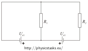
We have two identical 10 V electromotive voltage sources (power supplies) and two identical 20 Ω resistors connected together as shown in the figure.
Find the currents passing through each of the resistors. Let’s assume there is no internal resistance in any power supply.
Hint - Kirchhoff′s circuit laws
This task can be solved using Kirchhoff’s circuit laws:
Kirchhoff’s current law
The principle of conservation of electric charge implies that: At any node (junction) in an electrical circuit, the sum of currents flowing into that node is equal to the sum of currents flowing out of that node.Kirchhoff’s voltage law
This law is based on the conservation of energy whereby voltage is defined as the energy per unit charge: The directed sum of the electrical potential differences around any closed circuit must be zero.Hint - How to use Kirchhoff′s circuit laws
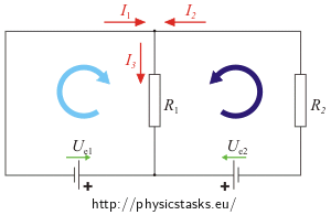
1. Draw arrows in the direction of the EMF (electromotive forces) of each power supply. They are oriented „from - to +“ (drawn green in the figure).
2. Draw current directions at each node (red arrows).
3. Choose oriented closed-loop/wires in the circuit (blue arrows).
Electrical wire is a closed-loop of the circuit, which doesn’t split (it makes a cycle).
!!!CAUTION!!! We can select the directions of currents (red arrows) and the electrical wires (blue arrows) randomly, but from then on we have to follow the choice!
4. Write the equations describing current at the nodes using I. Kirchhoff′s circuit law.
5. Use II. Kirchhoff’s circuit law to write an equation for each electrical loop in the circuit.
When writing down the equations take care about the signs. If the direction you are traveling around the loop has the same direction as the current passing through the resistor, the voltage drop should be counted negatively. If the directions are diferent, the voltage drop should be counted positively. If the loop has the same direction as the EMF, the power supply should be counted positively, otherwise negatively.
6. Kirchhoff’s laws provides us a set of linear equations. We obtain the values of each current by solving this set of equations.
If the value comes out negative, we have selected the oposite direction of the current (when drawing the arrows) in comparison to the real world.
Solution
Kirchhoff’s current law: \( I_1+I_2\,=\,I_3 \)
Kirchhoff’s voltage law applied on the loops (light and dark blue):
\[ R_1I_3\,=\,-U_{e1} \tag{light blue}\] \[ R_2I_2+R_1I_3\,=\,-U_{e2} \tag{dark blue}\]We know, that \( R_1\,=\,R_2 \),\( \hspace{10px}U_{e1}\,=\,U_{e2} \), so let’s subtract the first equation from the second one to get the value of I2:
\[ R_2I_2\,=\,U_{e1}-U_{e2}\,=\,0\] \[I_2\,=\,0\]Using Kirchhoff’s current law we get \(I_3\,=\,I_1\).
Let’s express I3 from Kirchhoff’s current law corresponding to the light blue arrow:
\[ R_1I_3\,=\,-U_{e1}\] \[I_3\,=\,-\,\frac{U_{e1}}{R_1}\]Numerical values
Solving Kirchhoff’s laws we have obtained values of the currents I2, I3:
\[I_2\,=\,0\,\mathrm{A}\] \[I_3\,=\,-\frac{U_{e1}}{R_1}\]Now we can calculate the value of the current I3:
\[I_3\,=\,-\frac{10}{20}\,\mathrm{A}\,=\,-0.5\,\mathrm{A}\]A negative result means, that the real current direction of I3 is oposite to the direction we have drawn (red arrow) in the diagram.
Answer
The currents passing through the resistors are I2 = 0 A, I3 = 0.5 A.


