The resistance of a wire cube
Task number: 285
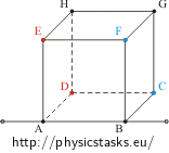
Find the resistance between different pairs of vertices of a wire cube.
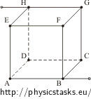
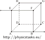
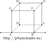
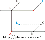
| a) between the vertices on the space diagonal | b) between the vertices on the face diagonal | c) between two vertices on one edge |
We will denote the resistance of one edge as R.
Hint 1
What happens if you connect the vertices with the same potential?
Which vertices have the same potential?
Hint 2
Plot the circuit into plane, connect vertices with the same potential.
Analysis
The voltage across the resistor equals to the potential difference between the terminals of the resistor. The potential at the vertex A has some given value. Our circuit branches in that vertex. Thanks to the symmetry of the cube we know that the currents through some of the loops (edges starting from vertex A) are the same. This means that the voltage across them is the same, too (because theirs resistance is the same), and that the potential at the ends of these edges is the same (the change of the potential from vertex A is the same).
We can merge the vertices with the equal potential into one junction as there would not be any current through a conductor connecting such vertices (same potential = same voltage). This modification of the circuit changes neither the quality nor the whole resistance of it.
We find the vertices with the same potential and merge them into one junction. Then we plot the circuit into plane and supplement each conductor with a resistor with resistance R.
Using the rules for calculations of the resistance of circuits connected in parallel and in series we calculate the total resistance of the cube.
Solution of part a) - Finding the resistance between the vertices on the space diagonal
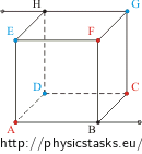
In this circuit the edges BA, BC and BF are equivalent, the current through them is the same. Therefore, the vertices A, C and F have the same potential. The resistance of the whole cube is not changed by merging these vertices into one.
The same situation holds for vertices D, E and G.
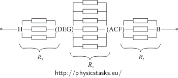
Let us merge the vertices A, C and F ( D, E and G) into one junction, redraw the circuit into the plane and supplement each cube’s edge with a resistor. The resistance of each edge is R.
The resistance R1 between the junctions H and (DEG) and the resistance R2 between the junctions (ACF) and B are equal to the resistance of three resistors R connected in parallel.
\[\frac{1}{R_1}\,=\,\frac{1}{R_2}\,=\,\frac{1}{R}+\frac{1}{R}+\frac{1}{R}\] \[R_1\,=\,R_2\,=\,\frac{R}{3}\]The resistance R3 between the junctions (DEG) and (ACF) is equal to the resistance of six resistors R connected in parallel.
\[\frac{1}{R_3}\,=\,\frac{6}{R}\] \[R_3\,=\,\frac{R}{6}\]The resistors R1, R2 and R3 are in series connection. Thus the total resistance of the cube between the vertices H and B is
\[R_{HB}\,=\,R_1+R_2+R_3\,=\,2\frac{R}{3}+\frac{R}{6}\] \[R_{HB}\,=\,\frac{5}{6}R\]Solution of the part b) - Finding the resistance between the vertices on the face diagonal
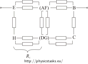
In this circuit the vertices A and F (D and G) are equivalent, their potential is the same. The resistance of the whole cube is not changed by merging these vertices into one. Let us merge the vertices A and F (D and G) into one junction, redraw the circuit into plane and supplement each cube edge with a resistor. The resistance of each edge is R.
Let us supplement each loop consisting of two resistors R in parallel connection as a single resistor whose resistance R1 is: \[\frac{1}{R_1}\,=\,\frac{1}{R}+\frac{1}{R}\] \[R_1\,=\,\frac{R}{2}\]Let us simplify the sketch of the circuit:
Due to the symmetry of the circuit there is no current through the resistor between the junctions (AF) and (DG). The junctions (AF) and (DG) have the same potential. Thus we can omit this resistor from our nest calculations.
Let us now consider each loop consisting of two resistors R in serial connection as a single resistor whose resistance R2 is
\[R_2\,=\,R_1+R\,=\,\frac{R}{2}+R\,=\,\frac{3}{2}R\]And we redraw the circuit once more:
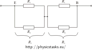
Now we have a circuit consisting of two resistors R3 connected in series. Each resistor R3 is composed of the resistors R1 and R2 in parallel connection.
Remember that \(R_1\,=\,\frac{R}{2}\), \(\hspace{10px} R_2\,=\,\frac{3}{2}R\).
We determine the resistance R3 from:
\[\frac{1}{R_3}\,=\,\frac{1}{R_1}+\frac{1}{R_2}\,=\,\frac{R_1+R_2}{R_1R_2} \] \[\frac{1}{R_3}\,=\,\frac{\frac{R}{2}+\frac{3}{2}R}{\frac{R}{2}\cdot \frac{3}{2}R} \,=\,\frac{\frac{4}{2}R}{\frac{3}{4}R^2}\,=\,\frac{2}{\frac{3}{4}R}\,=\,\frac{8}{3R}\] \[R_3\,=\,\frac{3}{8}R\]Thus the total resistance of the cube between the vertices E and B is:
\[R_{EB}\,=\,R_3+R_3\,=\,2R_3\,=\,2\frac{3}{8}R\] \[R_{EB}\,=\,\frac{3}{4}R\]Solution of the part c) - Finding the resistance between the vertices on one edge
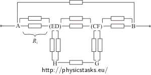
In this circuit the vertices E and D (F and C) are equivalent, they are on the same potential. The resistance of the whole cube is not changed by merging these vertices into one. Let us merge the vertices E and D (F and C) into one junction, redraw the circuit into the plane and supplement each cube edge with a resistor. The resistance of each edge is R.
Let us consider each loop consisting of two resistors R in parallel connection as a single resistor whose resistance R1 is:
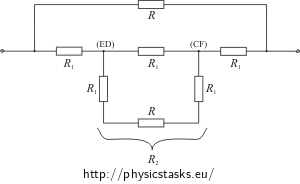
\[\frac{1}{R_1}\,=\,\frac{1}{R}+\frac{1}{R}\] \[R_1\,=\,\frac{R}{2}\]Let us simplify the sketch of the circuit:
The expression for the resistance R2 between the junctions (ED) and (CF) reads:
\[\frac{1}{R_2}\,=\,\frac{1}{R_1}+\frac{1}{\left(R_1+R+R_1\right)}\] \[\frac{1}{R_2}\,=\,\frac{1}{\frac{R}{2}}+\frac{1}{2\frac{R}{2}+R}\,=\,\frac{2}{R}+\frac{1}{2R}\,=\,\frac{5}{2R}\] \[R_2\,=\,\frac{2}{5}R\]The expression for resistance of the whole cube reads:
\[\frac{1}{R_{AB}}\,=\,\frac{1}{R}+\frac{1}{R_1+R_2+R_1}\]Inserting \(R_1\,=\,\frac{R}{2}\), \(R_2\,=\,\frac{2}{5}R\) we obtain RAB
\[ \frac{1}{R_{AB}}\,=\,\frac{1}{R}+\frac{1}{2\frac{R}{2}+\frac{2}{5}R}\,=\, \frac{1}{R}+\frac{1}{R+\frac{2}{5}R}\,=\,\frac{1}{R}+\frac{1}{\frac{7}{5}R} \] \[\frac{1}{R_{AB}}\,=\,\frac{1}{R}+\frac{5}{7R}\,=\,\frac{12}{7R}\]Thus the total resistance of the cube between the vertices A and B is
\[R_{AB}\,=\,\frac{7}{12}R\]Answer
The total resistance of the cube between the vertices H and B is \(\frac{5}{6}R\).
The total resistance of the cube between the vertices E and B is \(\frac{3}{4}R\).
The total resistance of the cube between the vertices A and B is \(\frac{7}{12}R\).
